Electronic parking braking method and braking releasing method

An electronic parking brake and brake release technology, which is applied in the direction of brake transmissions, brakes, vehicle components, etc., to achieve the effect of reducing the brake release stroke, reducing system costs, and high work efficiency

Active Publication Date: 2013-01-02
WANXIANGQIANCHAO CO LTD
View PDF3 Cites 7 Cited by
  • Summary
  • Abstract
  • Description
  • Claims
  • Application Information

AI Technical Summary

Problems solved by technology

[0004] In order to solve the above-mentioned technical problems existing in the existing electronic parking brake system, an electronic parkin

Method used


Image

  • Electronic parking braking method and braking releasing method
  • Electronic parking braking method and braking releasing method
  • Electronic parking braking method and braking releasing method

Examples


Embodiment Construction

[0030] In order to make the technical problems, technical solutions and beneficial effects solved by the present invention clearer, the present invention will be further described in detail below in conjunction with the accompanying drawings and embodiments. It should be understood that the specific embodiments described here are only used to explain the present invention, not to limit the present invention.

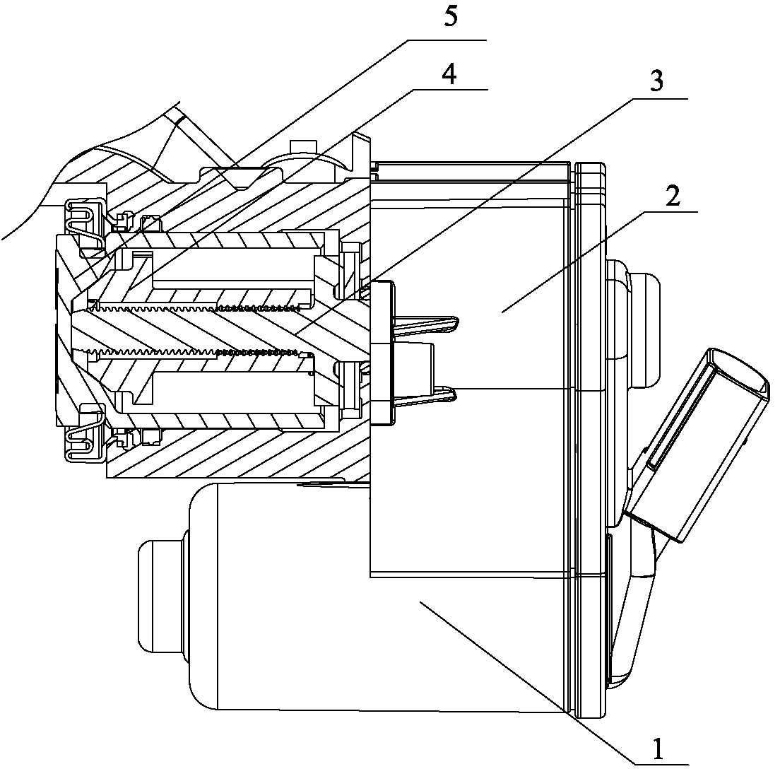
[0031] When the existing electronic parking brake system brakes or releases the brake, it generally measures the number of rotations of the motor through the added motor speed sensor, or sets a limit point between the screw rod and the screw sleeve (see the background for details). Technical part) to specifically determine the exact moment to stop the motor rotation, that is, to achieve the purpose of braking or releasing the brake. However, the method of adding a motor speed sensor not only makes the hardware structure complex and increases the cost, but also is not sui...


PUM


Abstract

The invention discloses an electronic parking braking method, which comprises the following steps of: an electronic control unit receives a braking instruction; the electronic control unit controls a motor to be electrified and started, and simultaneously drives a screw to rotate, so that a barrel pushes a piston to move towards the direction of a friction plate; and when a motor current collected by the electronic control unit reaches a first preset current value I1, the electronic control unit controls the motor to stop rotating. The invention also discloses an electronic parking braking releasing method, which comprises the following steps of: the electronic control unit receives a braking releasing instruction; the electronic control unit controls the motor to be electrified and started, and simultaneously drives the screw to move away from the direction of the friction plate; and when the motor current collected by the electronic control unit reaches a second preset current value I2, a second preset time is delayed, and the electronic control unit controls the motor to stop rotating. The electronic parking braking method and braking releasing method disclosed by the invention do not need additional hardware, but have high working efficiency, and can save energy.

Description

technical field [0001] The invention belongs to the field of vehicle braking, and in particular relates to an electronic parking braking method and a braking release method. Background technique [0002] With the continuous advancement of automobile technology, more and more automobiles have gradually changed from traditional mechanical control to electronic control. The electronic parking brake system uses electric energy to realize the functions of the traditional parking brake system. Existing electronic parking brake systems such as figure 1 As shown, it generally includes an electronic control unit (not shown in the figure), a motor 1, a transmission assembly 2 for reducing the motor speed and increasing the output torque of the motor, a screw 3, a screw sleeve 4, a piston 5 and a friction plate (friction plate Not shown in the figure), when the vehicle needs to be braked, the electronic control unit controls the motor to rotate forward, and at the same time drives the...

Claims


Application Information

Patent Timeline
IPC IPC(8): B60T13/74
Inventor 李齐丽
Owner WANXIANGQIANCHAO CO LTD
Why Eureka
Try Eureka