


Quick Research
Generate reliable direction feasibility study reports for your R&D in just a few steps.

Technical Q&A
Discover and master advanced knowledge NOW. Basics, ideas, possibilities, all at once.

Find Solutions
As an expert in R&D theories, this can generate solutions to your technical problems instantly.

Evaluate Feasibility
Analyze your overall solution with one click, know your potential R&D risks in advance.

Monitor Landscape
Get weekly tech updates, stay abreast of the latest tech innovations and key insights.
Asymmetrical multi-lobed annular seal for a connector assembly of a vehicle
A technology of seals and connectors, which is applied to the sealing of vehicle parts and engines, and the connection of sealing surfaces, etc., and can solve problems such as decline, shutdown productivity, etc.
- Summary
- Abstract
- Description
- Claims
- Application Information
AI Technical Summary
Problems solved by technology
Method used
Image

Examples
Embodiment Construction
[0019] The embodiments disclosed below are not intended to be exhaustive, nor are they intended to limit the disclosed content to the specific forms described in detail below. Specifically, the following examples are chosen for description so that others skilled in the art can utilize the enlightenment given by these examples.
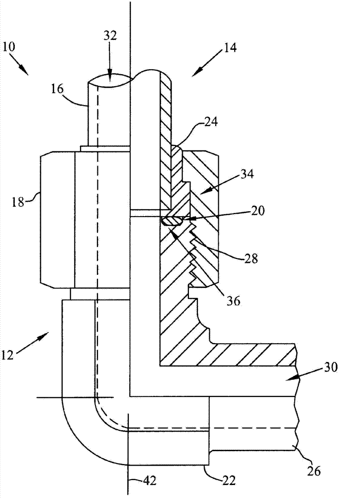
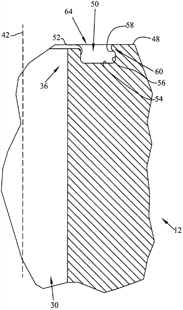
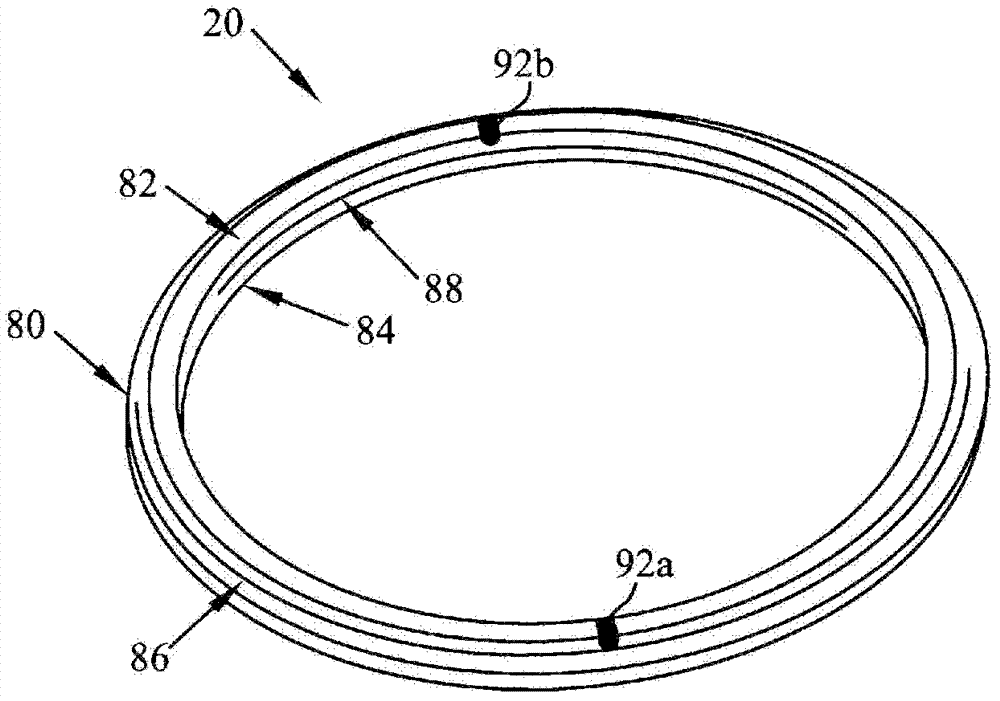
[0020] see figure 1 , wherein an exemplary connector assembly 10 is shown. The connector 10 includes a first connector 12 connected to a second connector 14 . In one embodiment, the connectors 12, 14 comprise attachments. A face seal 20 , described below, provides a sealed engagement between the first connector 12 and the second connector 14 . The first seal 12 schematically includes a tube or conduit 26 having a bend 22 and a mating end 36 . The second connection piece 14 is schematically a fitting 14 comprising a tube or conduit 16 and a socket 24 at the mating end 34 of the fitting 14 . The second connecting part 14 may also include a connector...
PUM
 Abstract
Description
Claims
Application Information
 - R&D Engineer
- R&D Manager
- IP Professional
- Industry Leading Data Capabilities
- Powerful AI technology
- Patent DNA Extraction
Browse by: Latest US Patents, China's latest patents, Technical Efficacy Thesaurus, Application Domain, Technology Topic, Popular Technical Reports.
© 2024 PatSnap. All rights reserved.Legal|Privacy policy|Modern Slavery Act Transparency Statement|Sitemap|About US| Contact US: help@patsnap.com