Aspirating face seal, and a related method thereof

Inactive Publication Date: 2012-10-04
GENERAL ELECTRIC CO
View PDF10 Cites 37 Cited by
  • Summary
  • Abstract
  • Description
  • Claims
  • Application Information

AI Technical Summary

Benefits of technology

[0005]There is a need for

Problems solved by technology

However, such sealing systems are subject to wear and increased leakage over time.
Thus, none of these seals meet all performance

Method used


Image

  • Aspirating face seal, and a related method thereof
  • Aspirating face seal, and a related method thereof
  • Aspirating face seal, and a related method thereof

Examples


Embodiment Construction

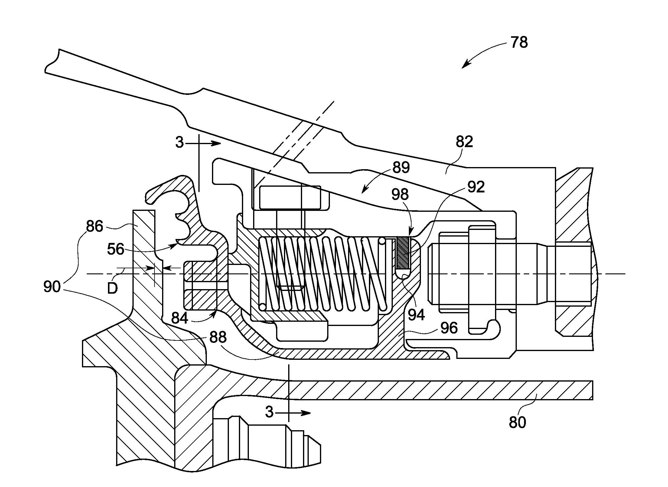
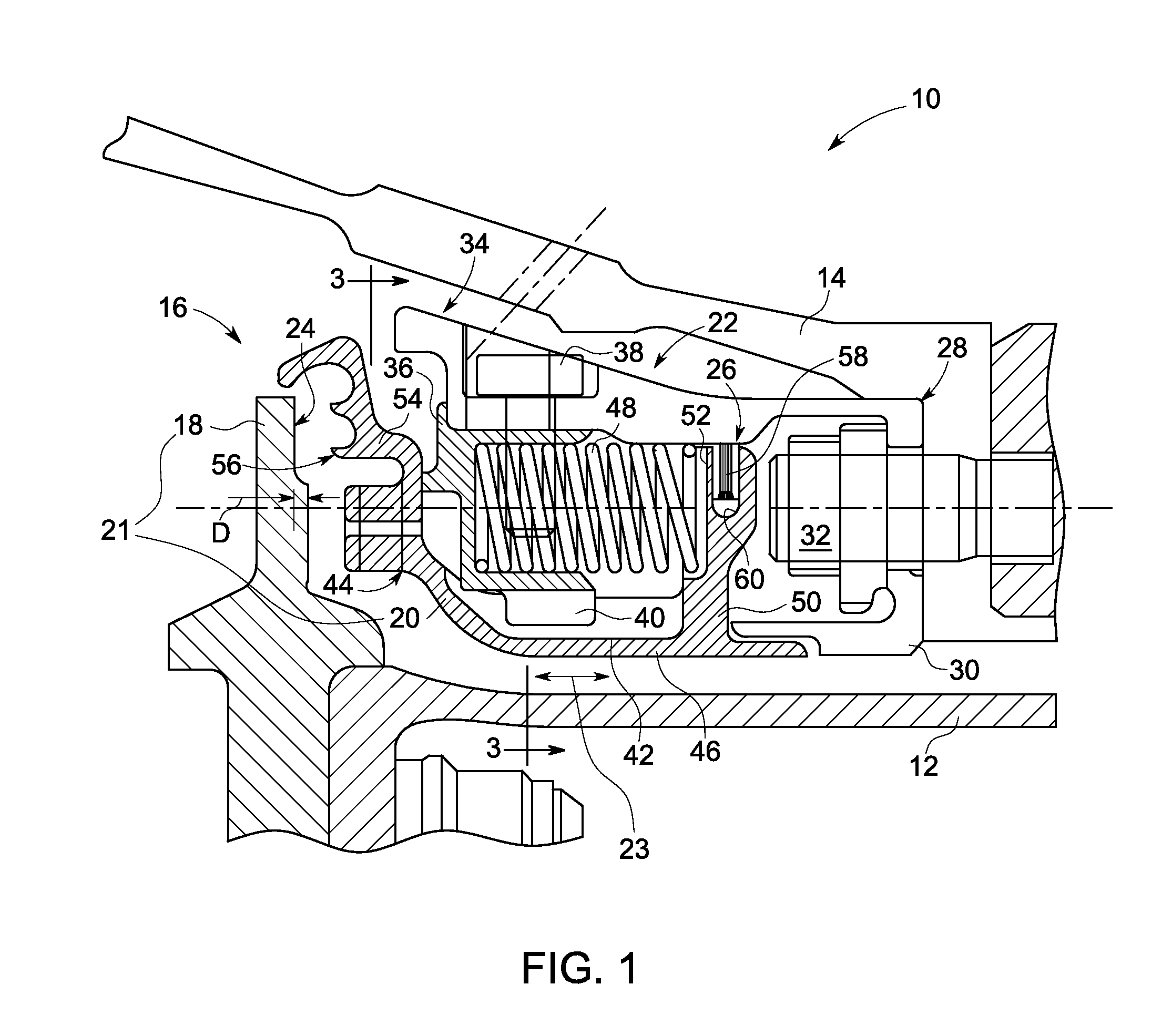
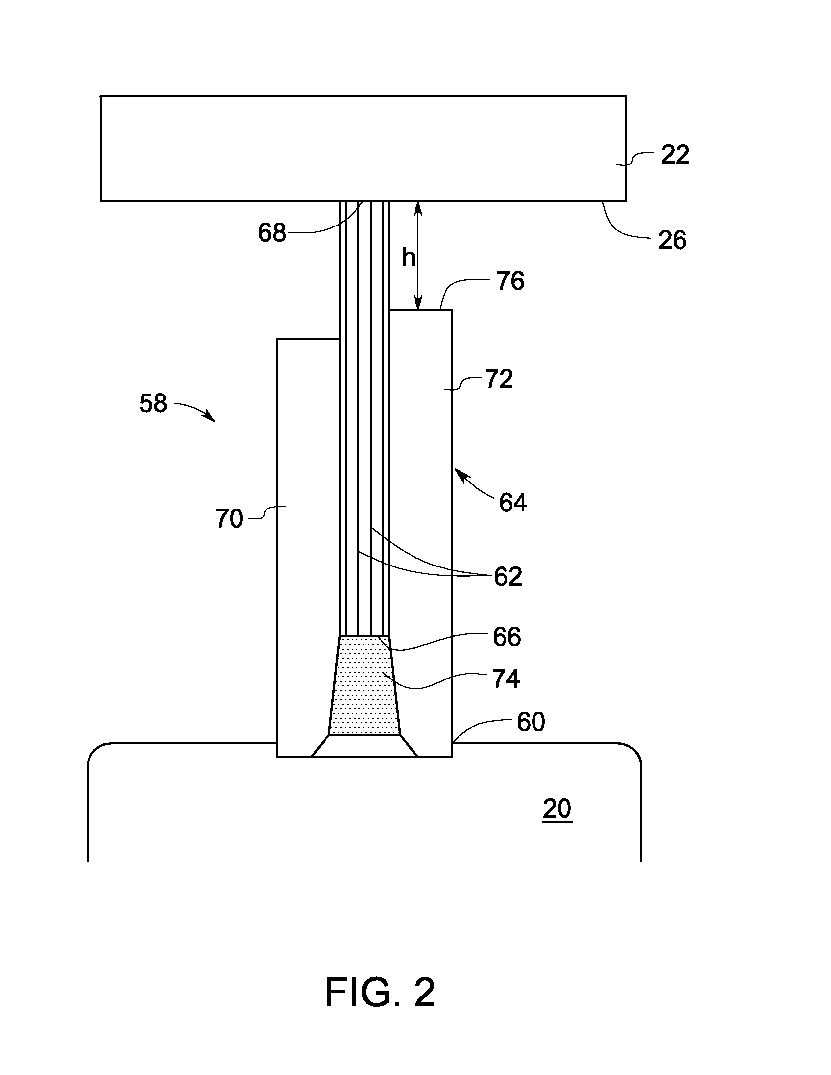
[0016]As discussed herein below with reference to embodiments of FIGS. 1-3, an aspirating face seal is disclosed. The exemplary aspirating face seal includes a primary seal having a first seal component and a second seal component. The first seal component is configured to be coupled to a rotor and rotatable with the rotor. A secondary seal having a plurality of flexible elements is disposed between the second seal component and a stator housing. A biasing device is coupled to the second seal component such that the second seal component is biased along an axial direction away from the first seal component during a non-operating condition. The second seal component is biased towards the first seal component during an operating condition. In a particular embodiment, a machine having the exemplary aspirating face seal is disclosed. In another embodiment, a method related to the aspirating face seal is disclosed. In some embodiments, the secondary seal is a brush seal. The usage of a b...


PUM


Abstract

An aspirating face seal includes a primary seal, a secondary seal, and a biasing device. The primary seal includes a first seal component and a second seal component. The first seal component is configured to be coupled to a rotor and rotatable with the rotor. The secondary seal includes a plurality of flexible elements and configured to be disposed between the second seal component and a stator housing. A biasing device is coupled to the second seal component such that the second seal component is biased along an axial direction away from the first seal component during a non-operating condition.

Description

BACKGROUND[0001]The invention relates generally to aspirating face seals, and more specifically to a secondary seal having a plurality of flexible elements of an aspirating face seal used in machines, for example, a gas turbine engine.[0002]Face seals are used to minimize leakage of a pressurized fluid through a gap between two components from a higher pressure area to a lower pressure area in a machine. Such seals have been used in rotating machines, for example, a steam turbine, a gas turbine, or the like. In applications such as gas turbine engines, aspirating face seals are used to minimize leakage of a fluid such as compressed air or combustion gases between a rotor and a stator. The seals applied to the gaps or leakage paths between the stator and the rotor should be able to compensate for variations in the gaps due to differential thermal and mechanical component expansions during the machine operating cycle.[0003]Conventional aspirating face seals typically have oppositely f...

Claims


Application Information

Patent Timeline
IPC IPC(8): F01D11/08F16J15/44
CPCF01D11/001F05D2240/58F05D2240/56F01D11/025F05D2260/38F16J15/3288F01D11/02
Inventor TURNQUIST, NORMAN ARNOLDERDMENGER, RODRIGO RODRIGUEZZHENG, XIAOQINGPANNEKEET, ROBBERT CHRISTIAANPARKER, KEITH MICHAEL
Owner GENERAL ELECTRIC CO
Why Eureka
Try Eureka