Centrifugal impeller and turbomachine

a centrifugal impeller and turbomachine technology, applied in the direction of liquid fuel engines, leakage prevention, motors, etc., can solve the problems of reducing the efficiency of the turbomachine, and achieve the effect of reducing the leakage flow

Active Publication Date: 2014-06-19
NUOVO PIGNONE TECH SRL
View PDF5 Cites 5 Cited by
  • Summary
  • Abstract
  • Description
  • Claims
  • Application Information

AI Technical Summary

Benefits of technology

[0015]An object of the present invention is to produce a centrifugal turbomachine and a centrifugal impeller providing an improved impeller eye sealing system to reduce the leakage flow between a casing of the turbomachine and the impeller.

Problems solved by technology

Fluid leakages through the eye seal 120 must be reduced as much as possible for the reason that the portion of fluid leaking from the outlet to the inlet side has to be compressed again through the impeller, thus reducing the efficiency of the turbomachine.
Fluid leakages through the eye seal must be reduced as much as possible also in an expander, for the reason that the portion of fluid leaking from the inlet to the outlet side does not flow through the impeller and therefore does not contribute to generate mechanical work on the shaft, thus reducing the efficiency of the turbomachine.

Method used


Image

  • Centrifugal impeller and turbomachine
  • Centrifugal impeller and turbomachine
  • Centrifugal impeller and turbomachine

Examples


second embodiment

[0034]A first and the present invention are shown in FIGS. 4 and 5, respectively.

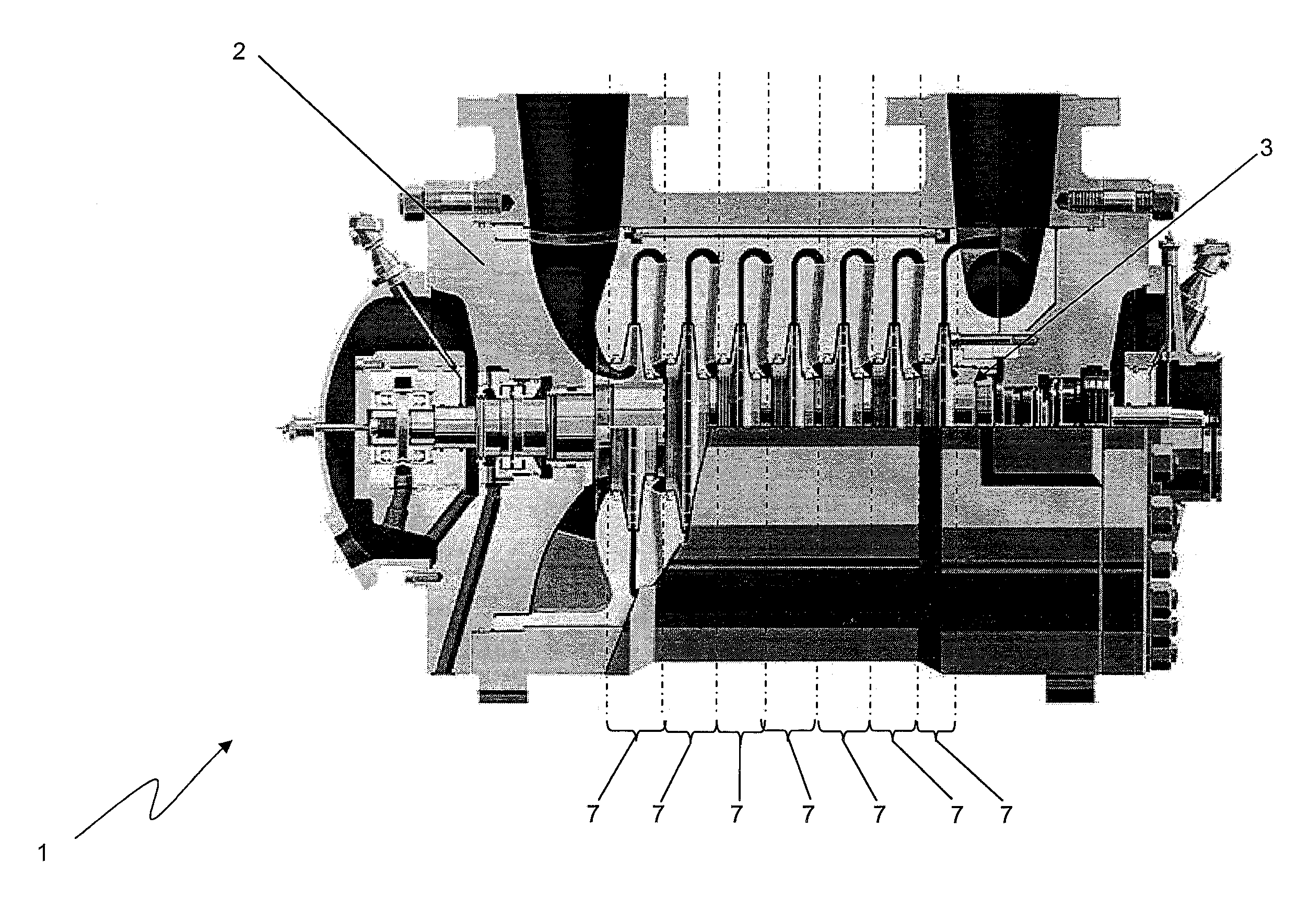
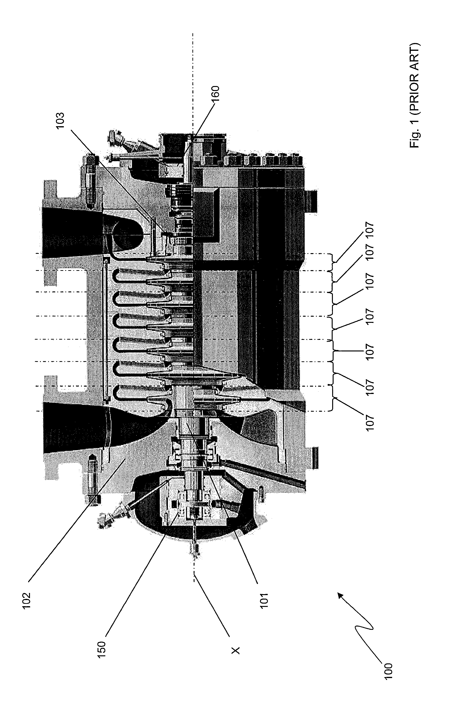
[0035]With reference to FIG. 4, a centrifugal turbomachine 1 is constituted by a centrifugal multistage compressor comprising a statoric casing 2 and a rotor assembly 3. The casing 2 and the rotor assembly 3 are subdivided into a plurality (seven) of stages 7 connected in series. For parts which are not described in the following, the compressor 1 must be considered conventional and identical to compressor 100 in FIGS. 1-3, described above.

[0036]Each stage 7 includes a centrifugal impeller 10 for a gaseous fluid flowing from an inlet low-pressure side 11 to an outlet high-pressure side 12 of the impeller 10. The centrifugal impeller 10 is of the shrouded type, comprising a shroud 19 on which an impeller eye 15 of the impeller 10 is provided. The impeller eye 15 defines the inlet low-pressure side 11, through which the fluid enters the impeller 10 along a direction substantially parallel to an axis of ro...

third embodiment

[0046]According to the present invention, a method for reducing leakages through the eye seal 20 of the centrifugal turbomachine 1 above described comprises the step of mounting the labyrinth eye seal 20 with the first tooth 21 a toward the inlet side 11 and the last portion 21e toward the outlet side 12 of the centrifugal impeller 10.

[0047]All the embodiments of the present invention allows to accomplish the object and advantages cited above.

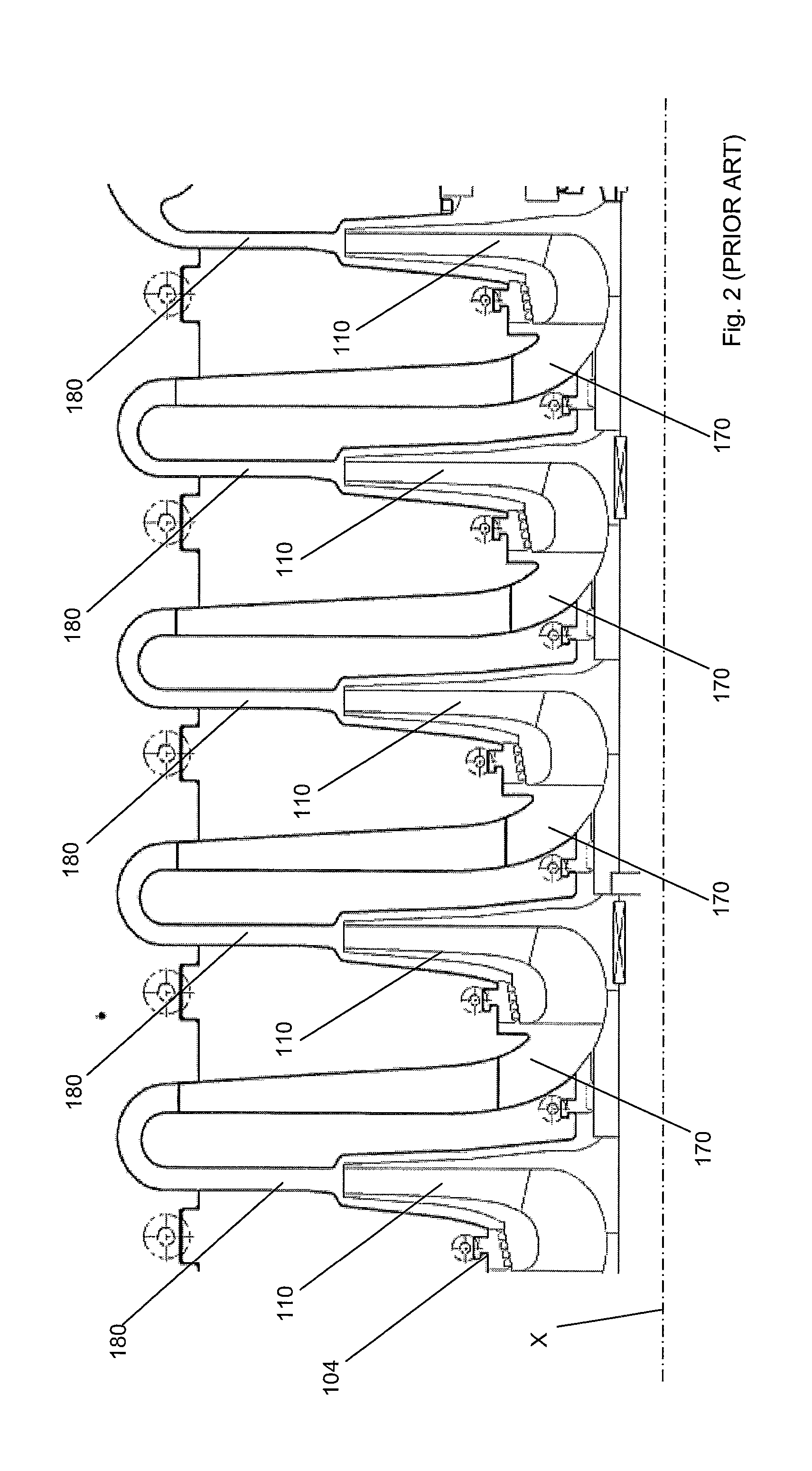
[0048]In addition the present invention allows to reach further advantages. In particular, the method above described can be used in refurbishing the conventional turbomachine 100 by substituting the plurality of centrifugal impellers 110 and a plurality of eye seals 120 with a plurality of impellers 10 and with a plurality of eye seals 20, thus obtaining the turbomachine 1 of the present invention, without modifying the other components of the conventional turbomachine.

[0049]In general, for all the embodiment of the present invention, a furthe...


PUM


Abstract

A centrifugal turbomachine comprising a casing, a rotor assembly comprising at least one centrifugal impeller for a fluid flowing from an inlet side to an outlet side of the impeller, and an eye seal extending between an impeller eye of the centrifugal impeller and the casing for preventing the fluid from leaking between the casing and the centrifugal impeller, wherein the eye seal comprises at least a first portion toward the inlet side and a last portion toward the outlet side of the impeller, the last portion being smaller in diameter than the first portion.

Description

BACKGROUND OF THE INVENTION[0001]The present invention relates to centrifugal turbomachines, to centrifugal impellers for turbomachines and to the related production methods, particularly, but not exclusively, for oil and gas applications.[0002]A centrifugal turbomachine is a rotary machine where mechanical energy is transferred between a working fluid and a centrifugal impeller. In oil and gas application, where the fluid is typically a gaseous fluid, centrifugal turbomachines include compressors and expanders. A compressor is a turbomachine which increases the pressure of a gaseous fluid through the use of mechanical energy. An expander is a turbomachine which uses the pressure of a working gaseous fluid to generate mechanical work on a shaft by using an impeller in which the fluid is expanded.[0003]In uncompressible fluid, e.g., water, centrifugal turbomachines include pumps and turbines, which transfer energy between the fluid and the impeller in a way analogous to compressors a...

Claims


Application Information

Patent Timeline
Patent Type & Authority Applications(United States)
IPC IPC(8): F01D11/02
CPCF01D11/02F01D5/043F04D29/162F04D29/284
Inventor IURISCI, GIUSEPPEBROGELLI, RICCARDO
Owner NUOVO PIGNONE TECH SRL
Why Eureka
Try Eureka