Embossed regenerator matrix for heat exchanger

a heat exchanger and matrix technology, applied in indirect heat exchangers, lighting and heating apparatus, heating types, etc., can solve the problems of reducing the traverse area of the passageway, and reducing the heat exchange efficiency of the regenerator, so as to increase the heat exchange efficiency of the matrix, and uniform height

Inactive Publication Date: 2005-05-17
AIRXCHANGE
View PDF26 Cites 37 Cited by
  • Summary
  • Abstract
  • Description
  • Claims
  • Application Information

AI Technical Summary

Benefits of technology

[0012]The embossments have a uniform height and include primary and secondary embossments. The primary embossments extend substantially parallel to the axis to divide the interlayer spaces into gas passageways and substantially resist circumferential gas leakage between the gas passageways. The primary embossments are also for aligning with the face seals to prevent circumferential gas leakage between the two counter-flowing air streams, and are successively spaced so that at most two successive primary embossments will align with the face seals. In this way, the total number of primary embossmen

Problems solved by technology

While such elongated embossments may maintain parallelism and prevent circumferential gas leakage, they replace parallel matrix surface area thereby reducing the heat exchange effectiveness of the regenerator.
However, while dimples provide a desirable high aspect ratio between layers, they unfortunately allow appreciable circumferen

Method used


Image

  • Embossed regenerator matrix for heat exchanger
  • Embossed regenerator matrix for heat exchanger
  • Embossed regenerator matrix for heat exchanger

Examples


Embodiment Construction

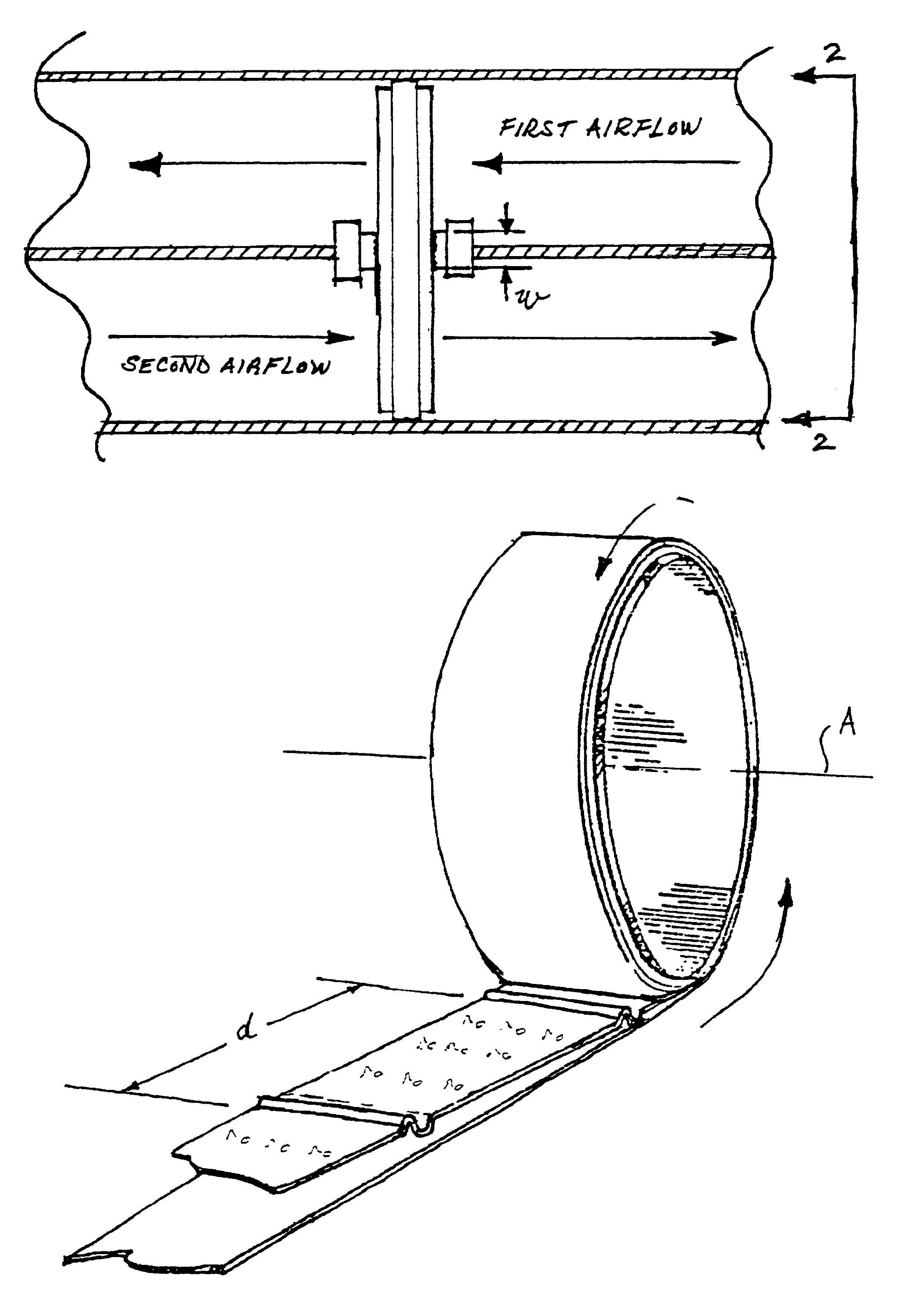
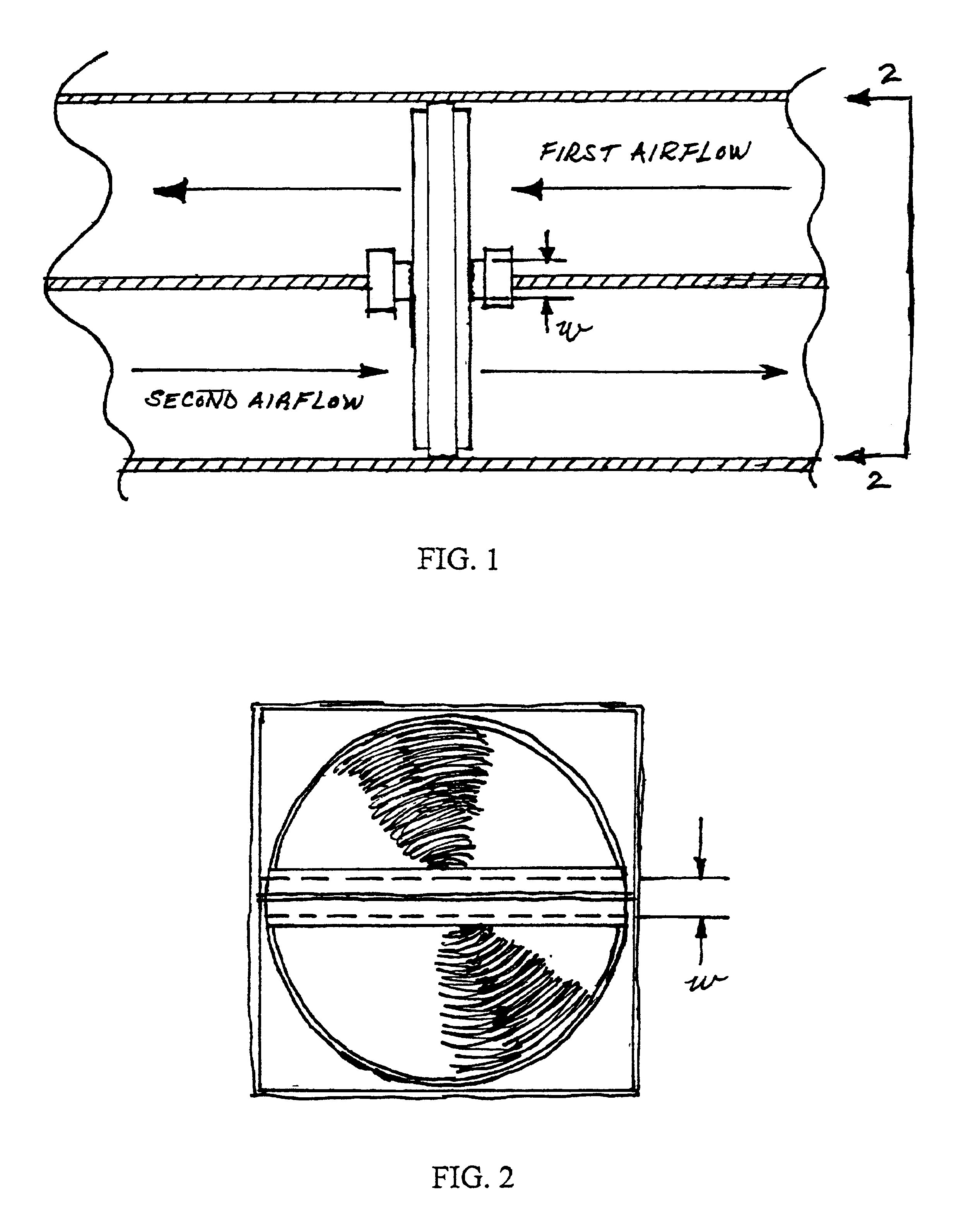
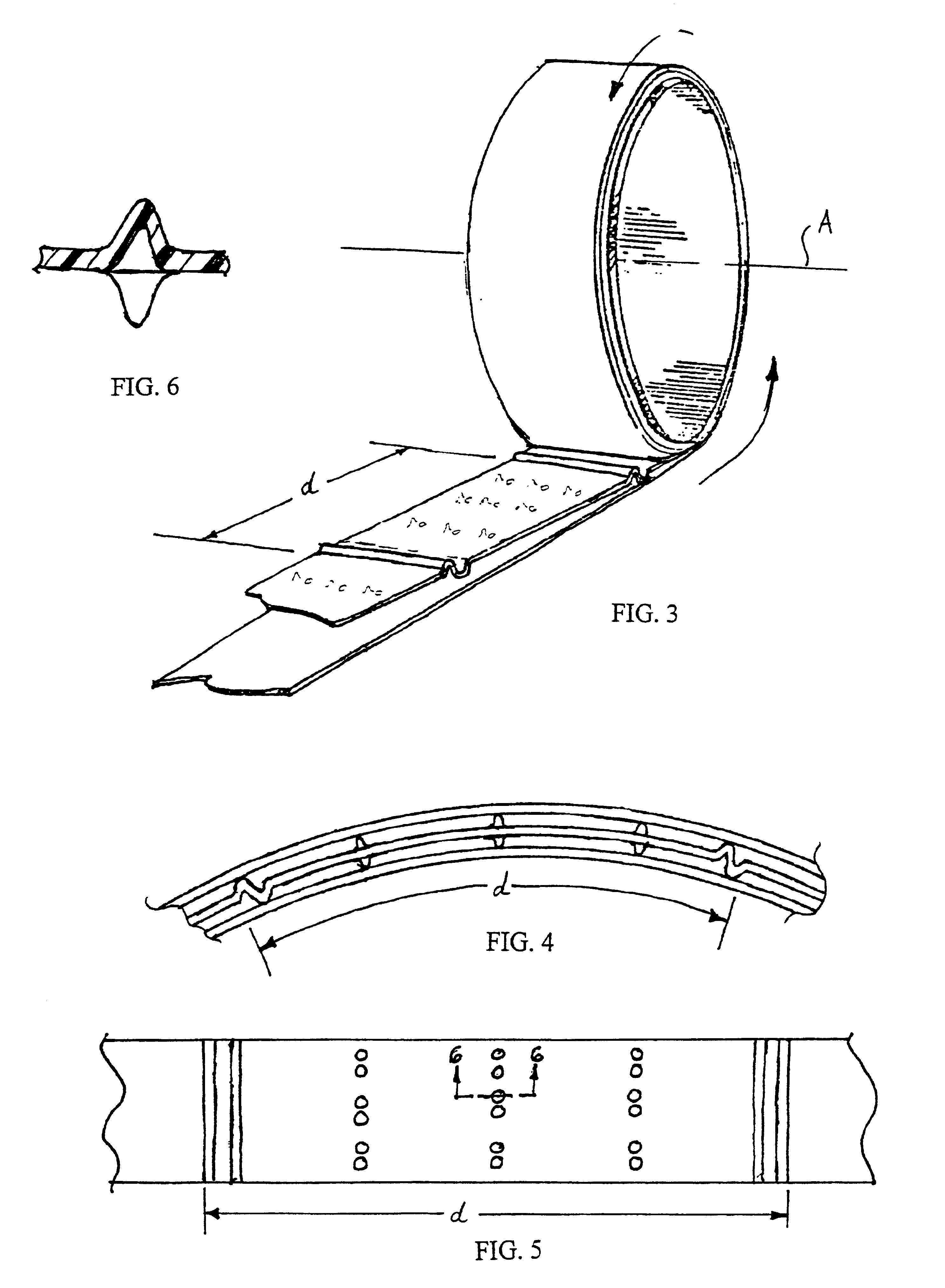
[0022]Referring to FIGS. 1 and 2, the present disclosure provides a regenerator matrix 10 for use as part of a rotary heat exchange wheel 12 in a counter-flow heat exchanger, or regenerator 14. The matrix 10 effects the transfer of heat and moisture between two counter-flowing air streams separated in part by face seals 16 having a predetermined width “w”.

[0023]As shown in FIGS. 1 and 2, the heat exchanger 14 includes an enclosure 18 having a flow chamber 20 and a counter-flow chamber 22 separated by a wall 24. A first airflow is received by the flow chamber 20, while a second airflow is received by the counter-flow chamber 22. As their names imply, the flow and counter-flow chambers 20, 22 direct the airflows in opposite directions.

[0024]The heat exchange wheel 12 is mounted within the enclosure 18 for simultaneous rotation through the flow chamber 20 and the counter-flow chamber 22, with an outer circumference of the wheel 12 forming a nearly air-tight seal between the wheel 12 an...


PUM


Abstract

A regenerator matrix for effecting the transfer of heat between two counter-flowing air streams separated in part by face seals. The matrix includes strips of material wound about an axis so as to provide a plurality of layers. The matrix also includes embossments located on at least some of the layers and providing interlayer spaces between at least some of the layers, such that the interlayer spaces extend through the matrix substantially parallel to the axis. The embossments have a uniform height and include primary and secondary embossments. The primary embossments extend substantially parallel to the axis to divide the interlayer spaces into gas passageways and substantially resist circumferential gas leakage between the gas passageways. The primary embossments are also for aligning with the face seals to prevent circumferential gas leakage between the two counter-flowing air streams, and are successively spaced so that at most two successive primary embossments will align with the face seals. The secondary embossments maintain the interlayer spaces at a substantially uniform spacing between the primary embossments, yet allow circumferential gas flow within the gas passageways.

Description

BACKGROUND OF DISCLOSURE[0001]1. Technical Field[0002]The present disclosure relates generally to regenerative heat exchangers and, more particularly, to a rotary heat exchange wheel for transferring heat between two counter-flowing air streams. Even more particularly, the present disclosure relates to a regenerator matrix of a rotary heat exchange wheel having wound layers of smooth film spaced apart with a combination of dimples and elongated embossments.[0003]2. Related Art[0004]Regenerator heat exchange devices or regenerators are well known for effecting the transfer of heat and moisture between two counter-flowing air streams. Such heat exchange devices are used, for example, in heating, ventilation and cooling (HVAC) systems to conserve energy within buildings. One type of regenerator is the rotary air-to-air heat exchanger, which is typically in the form of a rotary heat exchange wheel including a matrix of heat exchange material. When rotated through counter-flowing air str...

Claims


Application Information

Patent Timeline
IPC IPC(8): F23L15/00F23L15/02F28D19/00F28D19/04
CPCF23L15/02F28D19/042F24F2203/104Y10S165/399Y02E20/34
Inventor STEELE, DONALD F.
Owner AIRXCHANGE
Why Eureka
Try Eureka