Method and apparatus for embedding abrasive particles into substrates

a technology of abrasive particles and substrates, applied in the field of dressing bars, can solve the problems of large industrial waste generated by the process, scratches and damage to the bar, and the sharp outer edge 32/b> does not allow for efficient penetration of diamonds, etc., and achieves the effect of reducing or substantially lessening the excursion of the bar, and reducing the impact for

Inactive Publication Date: 2011-02-03
SCHWAPPACH KARL
View PDF0 Cites 23 Cited by
  • Summary
  • Abstract
  • Description
  • Claims
  • Application Information

AI Technical Summary

Benefits of technology

[0020]A hydrodynamic and / or hydrostatic fluid bearing (in one embodiment, air is the fluid) is maintained between the dressing bar and the substrate. Another method includes maintaining spacing between the dressing bar and the tin plate using a set of pads constructed onto the bar with a height matching the spacing. The fluid bearing produces stiffness between the plate and the dressing bar, while maintaining a constant clearance, to uniformly embed the abrasive particle into the substrate. A high stiffness minimizes or substantially lessens the excursion of the bar during the dressing bar and diamond interaction. The excursion of the dressing bar embeds diamonds into the soft plate with a substantially uniform height. The fluid used to suspend the bar with a constant clearance can be gas, liquid, or a combination thereof. As used herein, “topography following” refers to a dressing bar that can generally be designed to follow the topography of the plate at a generally uniform clearance above a substrate to reduce nanometer-scale height variations of abrasive particles on the surface. Also used herein, “topography averaging” refers to a dressing designed to filter the effects of topography of the plate leading to an average clearance above a substrate suppressing the effects of nanometer-scale height variations of abrasive particles on the surface.
[0021]The dressing bar interfaces with a gimbal mechanism. A preload mechanism places a preload onto the dressing bar through the gimbal mechanism. The preload mechanism and the gimbal mechanism permit the dressing bar to move vertically, and in pitch and roll relative to the substrate respectively. The fluid bearing provides vertical stiffness, and pitch and roll stiffness to the dressing bar, while controlling the spacing and pressure distribution across the fluid bearing features of the dressing bar. The high stiffness of the dressing bar reduces clearance loss and chatter emanating from particle interaction during embedding of the abrasive particles. Adjustments to certain variables, such as for example, dressing bar fluid bearing configuration, fluid bearing characteristics, pitch and roll stiffness, and preload, can be made to control the dressing bar spacing, attitude and fluid bearing stiffness.

Problems solved by technology

Such non uniform stress due to variable diamond height 26 causes scratches and damage to the bar.
The sharp outer edge 32 does not allow for efficient penetration of diamonds into the interface defined by the dressing bar and the substrate.
This process generates a large amount of industrial waste.
Current processes are wasteful since over 90 percent of the diamonds are lost and unrecoverable in the process.
Nano-diamonds are difficult to embed in the tin plate.
This difficulty leads to free diamonds.
The free diamonds increase the risk of damaging the slider bar.
Slider bars with trailing edges composed of metallic layers and ceramic layers present very severe challenges during lapping.
The variable polishing rates of the metallic and ceramic materials lead to severe recessions, sensor damage, and other problems. FIG. 3 illustrates the slider of FIG. 2 after lapping with a conventional diamond-charged substrate.
The diamond-charged plates cause large transducer protrusion and recession variations, substrate recession, microscopic substrate fractures leading to particle release during operation of the disk drive, scratches leading to transducer damage.
Forming the first substrate with sub-micron sized recesses and then inserting sub-micron sized abrasive grains, however, is not currently commercially viable.
Sorting sub-micron sized abrasive grains is also problematic.

Method used


Image

  • Method and apparatus for embedding abrasive particles into substrates
  • Method and apparatus for embedding abrasive particles into substrates
  • Method and apparatus for embedding abrasive particles into substrates

Examples


Embodiment Construction

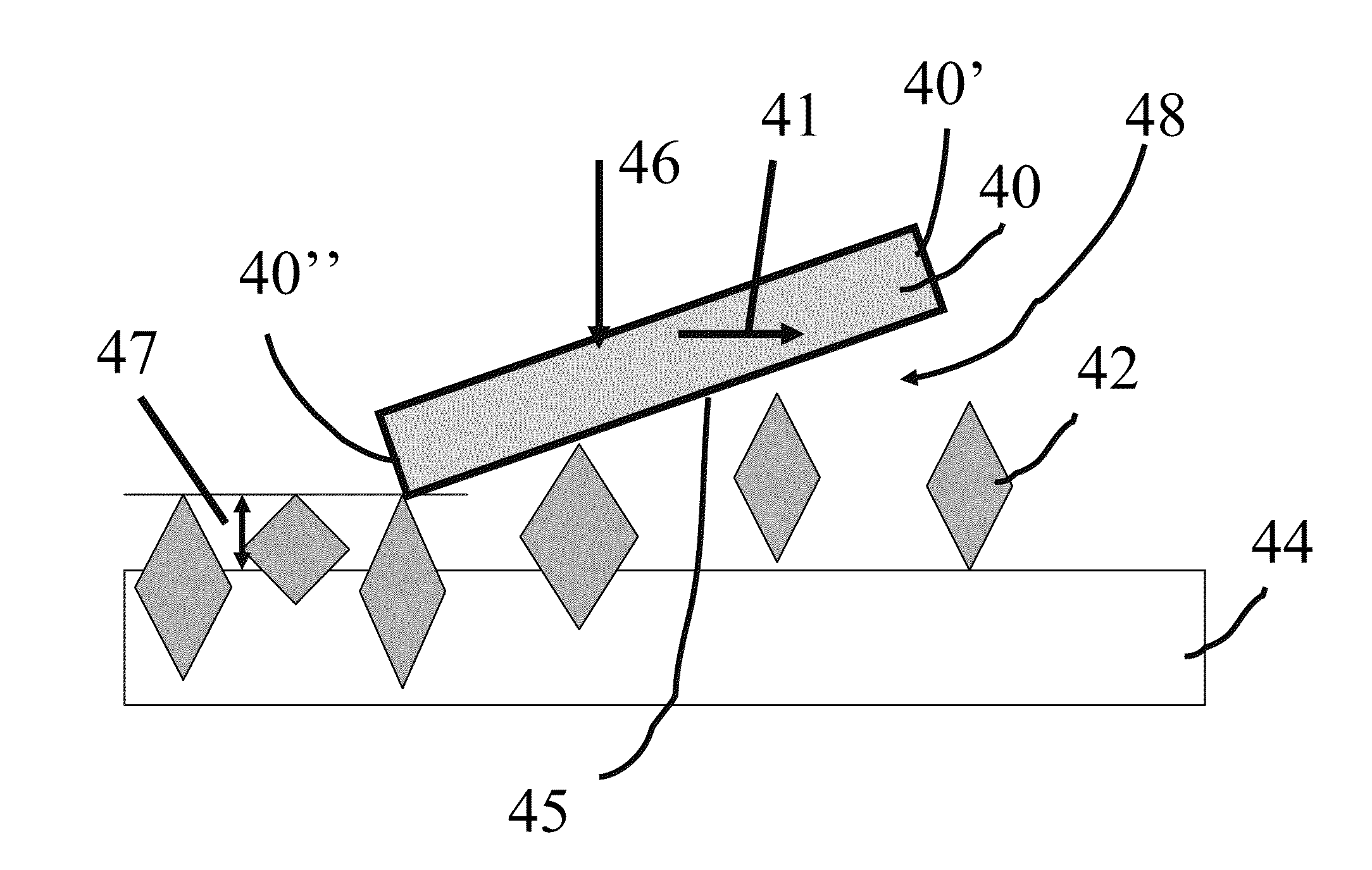
[0070]FIG. 4A is a schematic illustration of dressing bar 40 passing over a substrate 44. The dressing bar 40 is moved relative to the substrate 44, as indicated by arrow 41. The dressing bar 40 includes a leading edge 40′ and a trailing edge 40″. The dressing bar 40 uses a progressive interference to embed abrasive particles 42 into substrate 44. Progressive interference refers to a tapering gap interface 48 between active surface 45 of the dressing bar 40 and the substrate 44. In the illustrated embodiment, the dressing bar 40 is at an angle with respect to the substrate 44 to progressively embed the abrasive particles 42 into the substrate 44, resulting in a constant clearance 47 of the abrasive particles 42 relative to the substrate 44. The substrate 44 is also called a lapping plate after the particles 42 are embedded into the substrate 44. The interference can be adjusted by changing the clearance 47 at the trailing edge 40″ of dressing bar 40, the slope of the active surface ...


PUM

PropertyMeasurementUnit
diameteraaaaaaaaaa
thicknessaaaaaaaaaa
heightaaaaaaaaaa

Abstract

A dressing bars for embedding abrasive particles into a substrate at a substantially uniform height. Spacing pads, hydrostatic and/or hydrodynamic fluid bearing (air is the typical fluid) maintains a constant spacing and attitude between the dressing bar and the substrate. The fluid bearing permits the dressing bar to maintain a desirable stiffness between the lapping plate and the dressing bar. The bar geometry and fluid bearing design permits the bar to mitigate or compensate for the micrometer-scale and/or millimeter-scale wavelengths of waviness on the substrate, while maintaining a substantially constant clearance to uniformly embed the abrasive particle into the substrate.

Description

CROSS-REFERENCE TO RELATED APPLICATIONS[0001]This application claims the benefit of the filing date of U.S. Provisional Patent Application Ser. No. 60 / 220,149 filed Jun. 24, 2009, which is entitled “Constant Clearance Plate for Embedding Diamonds into Lapping Plates” which is hereby incorporated herein in its entirety by reference.FIELD OF THE INVENTION[0002]The present invention is directed to a dressing bar for embedding abrasive particles into a substrate at a substantially uniform height. Spacing pads, hydrostatic and / or hydrodynamic fluid bearing (air is the typical fluid) maintains a constant spacing and attitude between the dressing bar and the substrate. The fluid bearing permits the dressing bar to maintain a desirable stiffness between the lapping plate and the dressing bar. The bar geometry and fluid bearing design permits the bar to mitigate or compensate for the micrometer-scale and / or millimeter-scale wavelengths of waviness on the substrate, while maintaining a substa...

Claims


Application Information

Patent Timeline
Patent Type & Authority Applications(United States)
IPC IPC(8): B24D3/00B32B5/16B30B15/06
CPCB24D18/0054Y10T428/24893Y10T428/25
Inventor BOUTAGHOU, ZINE-EDDINE
Owner SCHWAPPACH KARL
Why Eureka
Try Eureka