Dressing bar for embedding abrasive particles into substrates

Inactive Publication Date: 2011-05-05
SCHWAPPACH KARL
View PDF104 Cites 33 Cited by
  • Summary
  • Abstract
  • Description
  • Claims
  • Application Information

AI Technical Summary

Benefits of technology

[0020]A hydrodynamic and / or hydrostatic fluid bearing (air is the typical fluid) is maintained between the dressing bar and the substrate. The fluid bearing permits the dressing bar to follow micrometer-scale and / or millimeter-scale wavelengths of waviness on the substrate, while maintaining a constant clearance, to uniformly embed the abrasive particle into the substrate. The abrasive particles are preferably partially embedded in the substrate before application of the dressing bar. The fluid can be gas, liquid, or a combination thereof. As used herein, “topography following” refers to a gimbaled dressing bar that generally follows millimeter-scale and / or micrometer-scale wavelengths of waviness at a generally uniform clearance above a substrate to reduce nanometer-scale height variations of abrasive particles on the surface.
[0021]The gimbal mechanism permits the dressing bar to move vertically, and in pitch and roll relative to the substrate. The fluid bearing provides vertical stiffness, and pitch and roll stiffness to the dressing bar, while controlling the spacing and pressure distribution across the fluid bearing features on the dressing bar. The high stiffness of the dressing bar reduces clearance loss and chatter emanating from particle interaction during embedding of the abrasive particles. Adjustments to certain variables, such as for example, the spacing, pitch and roll stiffness, and / or preload can be used to modify the force applied to the abrasive particles.
[0028]The present method and apparatus permits the height of the abrasive particles relative to the substrate to be precisely controlled. Consequently, abrasive articles made using the present method and apparatus can be tailored for particular applications and process parameters, such as for example the customers preferred lubricant. In one embodiment, a first abrasive article is prepared for use with a first lubricant having a first viscosity and a second abrasive article is prepared for use with a second lubricant having a second viscosity different from the first viscosity.

Problems solved by technology

If the gimbal is extremely stiff, the fluid bearing may not be able to form a pitch or roll angle.

Method used


Image

  • Dressing bar for embedding abrasive particles into substrates
  • Dressing bar for embedding abrasive particles into substrates
  • Dressing bar for embedding abrasive particles into substrates

Examples


Embodiment Construction

[0080]The entire content of U.S. Provisional Patent Application Nos. 61 / 174,472, filed Apr. 30, 2009; 61 / 187,658, filed Jun. 16, 2009; 61 / 220,149, filed Jun. 24, 2009; 61 / 221,554, filed Jun. 30, 2009; 61 / 232,425, filed Aug. 8, 2009; 61 / 232,525, filed Aug. 10, 2009; 61 / 248,194, filed Oct. 2, 2009; 61 / 267,031, entitled Dec. 5, 2009; and 61 / 267,030, filed Dec. 5, 2009, is hereby incorporated by reference.

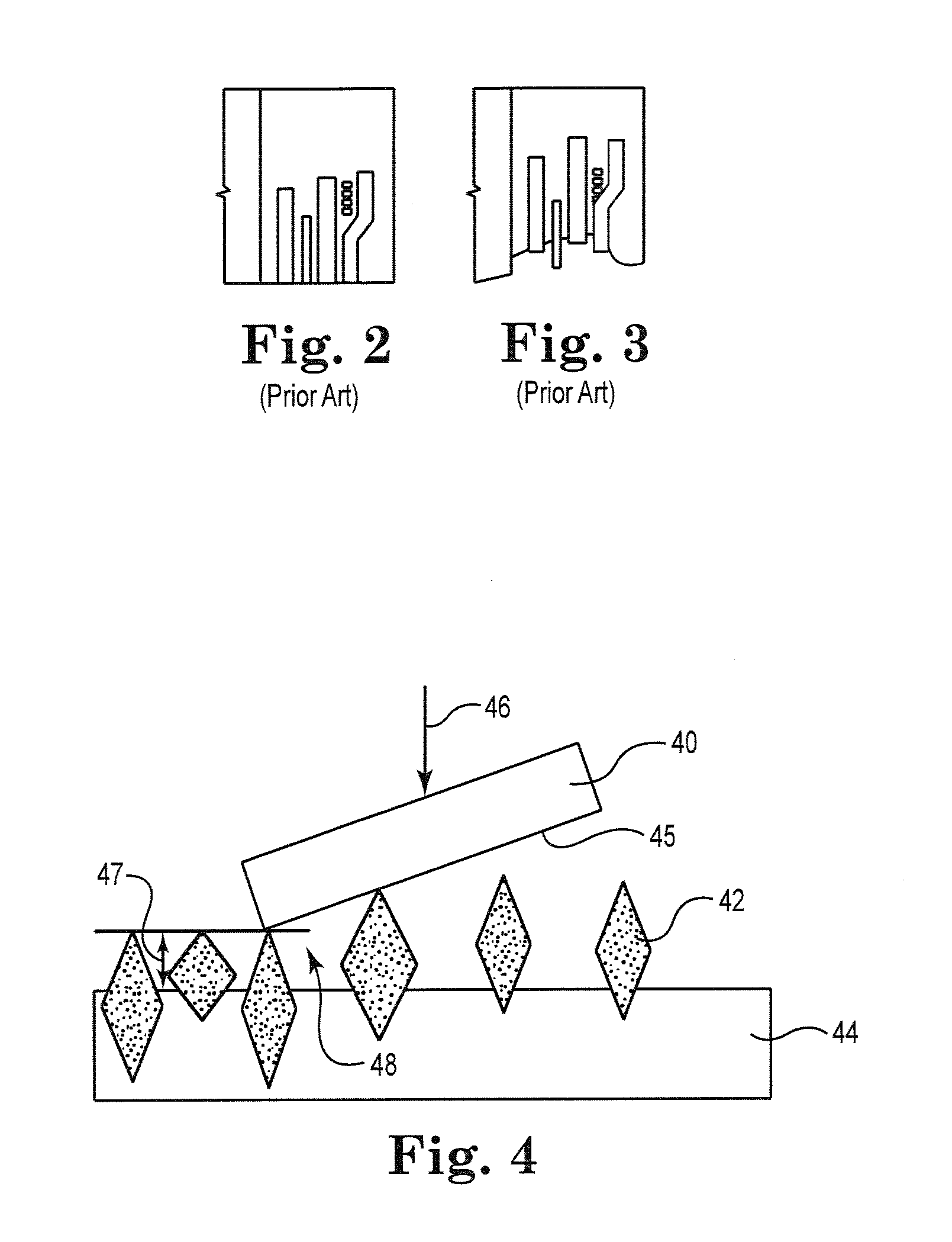
[0081]FIG. 4 is a schematic illustration of dressing bar 40 using progressive interference to embed abrasive particles 42 into substrate 44. Progressive interference refers to a tapering gap interface 48 between active surface 45 of the dressing bar 40 and the substrate 44. In the illustrated embodiment, the dressing bar 40 is at an angle with respect to the substrate 44 to progressively embed the abrasive particles 42 into the substrate 44, resulting in a constant clearance 47 of the abrasive particles 42 relative to the substrate 44. The interference can be adjusted by changing the c...


PUM

PropertyMeasurementUnit
Nanoscale particle sizeaaaaaaaaaa
Forceaaaaaaaaaa

Abstract

One or more individually gimballed dressing bars for embedding abrasive particles into a substrate at a substantially uniform height. A hydrostatic and / or hydrodynamic fluid bearing (air is the typical fluid) is maintained between the dressing bar and the substrate. The fluid bearing permits the dressing bar to follow micrometer-scale and / or millimeter-scale wavelengths of waviness on the substrate, while maintaining a constant clearance, to uniformly embed the abrasive particle into the substrate.

Description

RELATED APPLICATIONS[0001]The present application claims the benefit of U.S. Provisional Patent Application Nos. 61 / 174,472 entitled Method and Apparatus for Atomic Level Lapping, filed Apr. 30, 2009; 61 / 187,658 entitled Abrasive Member with Uniform Height Abrasive Particles, filed Jun. 16, 2009; 61 / 220,149 entitled Constant Clearance Plate for Embedding Diamonds into Lapping Plates, filed Jun. 24, 2009; 61 / 221,554 entitled Abrasive Article with Array of Gimballed Abrasive Members and Method of Use, filed Jun. 30, 2009; 61 / 232,425 entitled Constant Clearance Plate for Embedding Abrasive Particles into Substrates, filed Aug. 8, 2009; 61 / 232,525 entitled Method and Apparatus for Ultrasonic Polishing, filed Aug. 10, 2009; 61 / 248,194 entitled Method and Apparatus for Nano-Scale Cleaning, filed Oct. 2, 2009; 61 / 267,031 entitled Abrasive Article with Array of Gimballed Abrasive Members and Method of Use, entitled Dec. 5, 2009; and 61 / 267,030 entitled Dressing Bar for Embedding Abrasive Pa...

Claims


Application Information

Patent Timeline
IPC IPC(8): B24B1/00B24B53/12B24B37/00B24D3/00
CPCB24B37/14B24D18/00B24B53/12B24B53/017
Inventor BOUTAGHOU, ZINE-EDDINESCHWAPPACH, KARL G.
Owner SCHWAPPACH KARL
Why Eureka
Try Eureka