Composite coiled tubing end connector

a technology of coiled tubing and end connector, which is applied in the direction of hose connection, drilling pipe, mechanical equipment, etc., can solve the problems of steel coiled tubing suddenly fracture and fail, risk to personnel, and damage to the coiled tubing, so as to resist deformation of the pipes, enhance the fluid seal, and inhibit the delamination of the layers

Inactive Publication Date: 2009-03-03
FIBERSPAR
View PDF68 Cites 36 Cited by
  • Summary
  • Abstract
  • Description
  • Claims
  • Application Information

AI Technical Summary

Benefits of technology

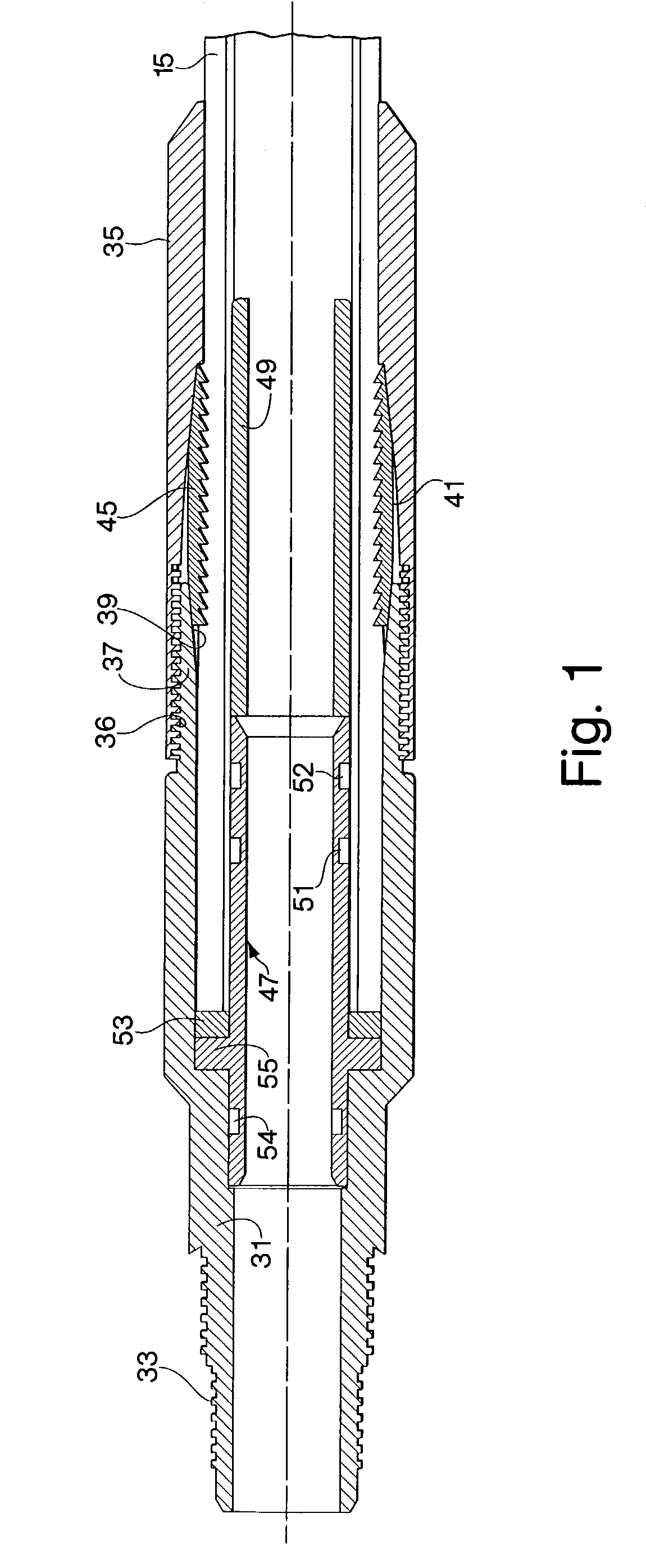
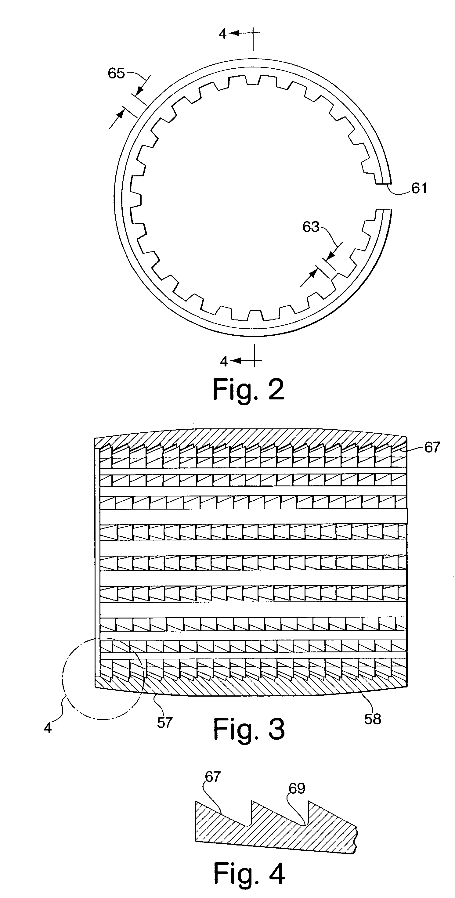
[0029]The double seal carrier of the pipe-to-pipe connector of the present invention is preferably of single piece, unitary construction. The one piece double seal carrier establishes a seal between the connector and the composite pipes and, in addition, resists deformation of the pipes due to the radially compressive forces applied by the first and second slips. Preferably, the double seal carrier is positioned within the first and second composite pipes such that the first seal member is located radially opposite the first slip and the second seal member is located radially opposite the second slip. As discussed above, this arrangement can enhance the fluid seal provided by the seal members. The double seal carrier can include a raised annular shoulder that axially engages both the end of the first pipe and the end of the second pipe.
[0030]In accordance with one embodiment of the present invention, the seal carrier of the end connector can be replaced with a generally annular, integral seal positioned at the end of the composite pipe. The integral seal can be formed from a portion of a layer of the pipe to provide the primary fluid seal between the composite pipe and the end connector. By folding a layer of the composite member radially outward at the end of the composite pipe, the integral seal can be formed having a seal surface for engaging the service end of the end connector in sealing relationship. Preferably, the layer is folded into contact with the remaining layers of the composite pipe to inhibit delamination of the layers from fluid leakage through the end of the pipe. Any layer or layers of the composite pipe can be used to form the integral seal. It is preferable, however, for the innermost layer of the composite pipe to be used to create the integral seal. In this manner, a substantial portion of the radially extending surface of the pipe end is enclosed by the integral seal. Alternatively, the outermost layer of the composite pipe can be utilized to create the integral seal. In this case, the outermost layer can be folded radially inward to form the integral seal.
[0031]In accordance with a method of coupling a connector to a composite pipe of the present invention, the integral seal can be formed by removing the outer layers of the composite pipe at the end of the pipe to expose a portion of an inner layer of the composite pipe. The exposed portion of the inner layer can be heated until the material forming the layer becomes pliable. The exposed portion can then be folded such that the outer surface of the layer engages the ends of the outer layers of the pipe. The inner surface of the folded layer provides the seal surface of the integral seal. Additionally, the ends of the o

Problems solved by technology

Unfortunately, repeated spooling and use causes fatigue damage and the steel coiled tubing can suddenly fracture and fail.
The hazards of the operation and the risk to personnel and the high economic cost of failure in down time to conduct fishing operations forces the product to be retired before any expected failure after a relatively few number of trips into a well.
The cross section of steel tubing expands during repeated use resulting in reduced wall thickness and higher bending strains with associated reduction in the pressure carrying capability.
Steel coiled tubing presently in service is generally limited to internal pressures of about 5000 psi.
Higher internal pressure significantly reduces the integrity of coiled tubing so that it will not sustain continuous flexing and thus severely limits its service life.
Tension and compression forces on coiled tubing are severe in that the tubing may be forced into or pulled from a borehole against frictional forces in excess of 20,000 lbf.
However, the

Method used


Image

  • Composite coiled tubing end connector
  • Composite coiled tubing end connector
  • Composite coiled tubing end connector

Examples


Embodiment Construction

[0075]While this invention is directed generally to providing connectors for composite spoolable pipe, the disclosure is directed to a specific application involving line pipe, coiled tubing service and downhole uses of coiled tubing. Composite coiled tubing offers the potential to exceed the performance limitations of isotropic metals, thereby increasing the service life of the pipe and extending operational parameters. Composite coiled tubing is constructed as a continuous tube fabricated generally from non-metallic materials to provide high body strength and wear resistance. This tubing can be tailored to exhibit unique characteristics which optimally address burst and collapse pressures, pull and compression loads, as well as high strains imposed by bending. This enabling capability expands the performance parameters beyond the physical limitations of steel or alternative isotropic material tubulars. In addition, the fibers and resins used in composite coiled tubing construction...


PUM

PropertyMeasurementUnit
Energyaaaaaaaaaa

Abstract

Connectors for attaching a composite pipe to a service member are described herein. In one embodiment, a connector can include a service end, a slip nut, a slip, a seal carrier, and an energy conductor. The slip nut can be disposed about the outer surface of the pipe and can be engaged by the service end. The slip can be positioned about the outer surface of the pipe and can be engaged by the service end and the slip nut to compress the slip into gripping contact with the pipe. The seal carrier can be positioned in a bore of the pipe at a location radially opposite the slip to resist deformation of the pipe when the slip is compressed into gripping contact with the pipe. The energy conductor can be embedded within and surrounded by a material of the service end for connection with an energy conductor within the composite pipe.

Description

REFERENCE TO RELATED APPLICATIONS[0001]This application is a continuation-in-part of U.S. patent application Ser. No. 09 / 410,605, filed Oct. 1, 1999, which is a continuation-in-part of U.S. patent application Ser. No. 09 / 368,333, filed Aug. 3, 1999, which is a continuation of U.S. patent application Ser. No. 08 / 721,135, filed Sep. 26, 1996, which claims priority to U.S. Provisional Application Ser. No. 60 / 005,377, filed Sep. 28, 1995.[0002]This application is also a continuation-in-part of U.S. patent application Ser. No. 09 / 678,577, filed Oct. 3, 2000, which claims priority to U.S. Provisional Application Ser. No. 60 / 157,614, filed Oct. 4, 1999.[0003]All of the above-referenced patent applications are expressly incorporated by reference herein in their entireties.FIELD OF THE INVENTION[0004]This application relates generally to connectors for use with a spoolable pipe constructed of composite material and more particularly to a field serviceable connector for use in such applicatio...

Claims


Application Information

Patent Timeline
IPC IPC(8): H02G15/24E21B17/02E21B17/04E21B17/20F16L19/08F16L33/22F16L47/04
CPCE21B17/02E21B17/04E21B17/20F16L19/083F16L19/086F16L33/22F16L47/04E21B17/041
Inventor BROTZELL, ARTHUR D.FOWLER, JR., STEWART H.THO, CHANTAL
Owner FIBERSPAR
Why Eureka
Try Eureka