Corrugated pipe with outer layer

a corrugated pipe and outer layer technology, applied in the direction of flexible pipes, pipe protection, pipe damage/wear prevention, etc., can solve the problems of corrugated pipes that cannot be used, polymer, and brittle, and use of stiffer materials to make corrugated plastic pipes, so as to improve the resistance to deformation

Active Publication Date: 2014-05-27
ADVANCED DRAINAGE SYST
View PDF204 Cites 15 Cited by
  • Summary
  • Abstract
  • Description
  • Claims
  • Application Information

AI Technical Summary

Benefits of technology

[0014]Another exemplary embodiment of the present disclosure provides a method of improving the resistance to deformation of a corrugated pipe having a smooth inner wall fused to an outer wall defined by annular crests and valleys. The method includes: fixing an outer layer having adjacent annular concave portions and convex portions to the outer wall with the concave portions being aligned with corrugation valleys of the outer wall so that each concave portion of the outer layer extends between at least two corrugation crests.

Problems solved by technology

Traditionally, drainage pipe was made from clay or concrete, which caused the pipe to be heavy, expensive, and brittle.
There are two basic ways that polymer, corrugated pipe can fail in use: by deforming excessively or by fracturing.
Using stiffer material to make a corrugated plastic pipe is disadvantageous because the pipe must be able to deflect under load to a certain degree without cracking or buckling.
Thickening the pipe walls is also disadvantageous because it adds material cost and increases weight to the pipe, which increases shipping and handling costs.
Although the double wall pipe illustrated in FIG. 1 may have sufficient flexibility, its centroid is too far from the middle of its sheet thickness to provide sufficiently uniform stress distribution during deformation.
Moreover, the double wall pipe profile provides insufficient resistance to pipe buckling, for a given amount of raw material.
Therefore, the double wall pipe may not be stiff enough to provide installation insensitivity and long-term durability.

Method used


Image

  • Corrugated pipe with outer layer
  • Corrugated pipe with outer layer
  • Corrugated pipe with outer layer

Examples


Embodiment Construction

[0030]Reference will now be made in detail to the exemplary embodiments of the invention, examples of which are illustrated in the accompanying drawings.

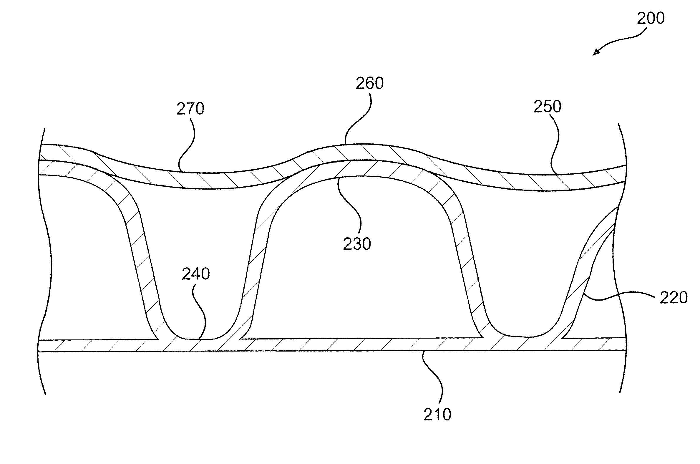
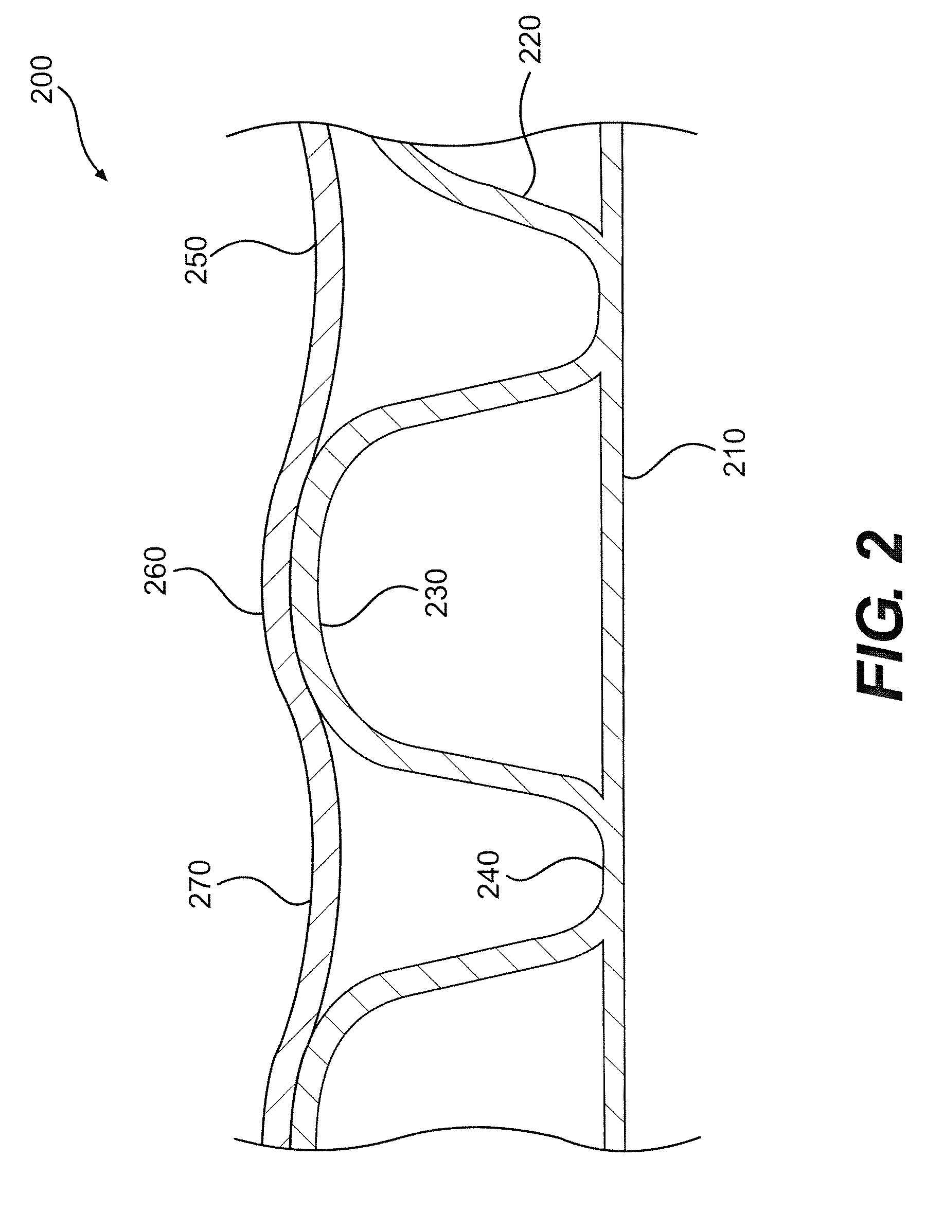
[0031]FIG. 2 illustrates a cross-section of a sidewall of an exemplary embodiment of a three-wall, corrugated pipe consistent with the present invention. The illustrated section of pipe wall 200 preferably includes a smooth inner wall 210 and a corrugated outer wall 220. The inner wall 210 has a smooth interior surface to improve the hydraulics of fluid traveling through the pipe. The corrugated outer wall 220 provides a high strength-to-weight ratio for the pipe wall 200.

[0032]The corrugated outer wall 220 includes corrugation crests 230 and corrugation valleys 240. On top of the corrugated outer wall 220 is an outer layer 250 of the pipe wall 200 that includes convex portions 260 and concave portions 270. The concave portions 270 of the outer layer 250 are generally aligned with the valleys 240 and extend between adjacent crests 2...


PUM


Abstract

A pipe having an axially extending bore defined by a smooth inner wall fused to a corrugated outer wall is provided. The corrugated outer wall has axially adjacent, annular, outwardly-extending crests separated by valleys. The pipe further includes an outer layer fused to the outer wall, the outer layer having adjacent concave portions and convex portions, the concave portions being aligned with corrugation valleys of the outer wall so that each concave portion of the outer layer extends between at least two corrugation crests. A method of improving the resistance to deformation of a corrugated pipe having a smooth inner wall fused to an outer wall defined by annular crests and valleys is also provided.

Description

RELATED APPLICATION[0001]This application is a continuation-in-part of U.S. patent application Ser. No. 11 / 078,323, which was filed on Mar. 14, 2005, now U.S. Pat. No. 7,484,535 and which is incorporated herein by reference.FIELD OF THE INVENTION[0002]The present invention relates generally to corrugated pipe having an additional outer layer, and more particularly, to such a corrugated pipe for use in the drainage of soil and transportation of surface water by gravity.BACKGROUND OF THE INVENTION[0003]Corrugated pipe has been used in the drainage of water-saturated soil in various agricultural, residential, recreational, or civil engineering and construction applications, such as for storm sewers. Traditionally, drainage pipe was made from clay or concrete, which caused the pipe to be heavy, expensive, and brittle. In order to improve the cost-effectiveness, durability, and ease-of-installation of drainage pipes, it is now common in the art to manufacture them from various materials ...

Claims


Application Information

Patent Timeline
Patent Type & Authority Patents(United States)
IPC IPC(8): F16L11/00
CPCF16L57/00F16L9/00F16L9/06
Inventor GODDARD, JAMES B.KURDZIEL, JOHN M.
Owner ADVANCED DRAINAGE SYST
Why Eureka
Try Eureka