Composite Exterior Siding Panel With Interlock

Active Publication Date: 2013-06-27
PLY GEM INDS
View PDF1 Cites 14 Cited by
  • Summary
  • Abstract
  • Description
  • Claims
  • Application Information

AI Technical Summary

Benefits of technology

[0008]It is another object of the invention to provide a composite exterior siding panel that is lightweight and easy to install by an untrained homeowner with standard tools.
[0009]It is another object of the invention to provide a composite exterior siding panel that is tough, durable and capable of withstanding impacts from large diameter hail.
[0010]It is another object of the invention to provide a composite exterior siding panel that facilitates drainage of moisture trapped between the paneling and the building structure through weep slots in the rear face of the panel that start near the first flat and proceed past the inflection point of the panel.
[0011]It is another object of the invention to provide a composite exterior siding panel that includes a locking leg extending rearwardly from the back face of the panel and that also extends nominally downwardly toward the bottom edge of the panel and that extends longitudinally along the entire length of the panel. The locking leg creates a pocket for insertion of the top edge of a second panel disposed below the first panel to precisely define the positional relationship between the first and second panels.
[0012]It is another object of the invention to provide a composite exterior siding panel with a top portion and a bottom portion of a panel separat

Problems solved by technology

The siding must be capable of protecting the structure from blisteringly hot sunlight that can induce thermal expansion and unattractive buckling of the siding.
Siding panels that allow wind to gain access to the back surface, or the surface adjacent to the building structure, can experience tremendous loads capable of literally peeling the siding from the building.
Numerous siding panel designs exist in the market place; however, all are either lacking in some functional aspect or are prohibitively expensive, difficult to install or require extensive training and costly tools for proper installation.
The consequence of such involved training and the acquisition of expensive tools is that these costs

Method used


Image

  • Composite Exterior Siding Panel With Interlock
  • Composite Exterior Siding Panel With Interlock
  • Composite Exterior Siding Panel With Interlock

Examples


Example

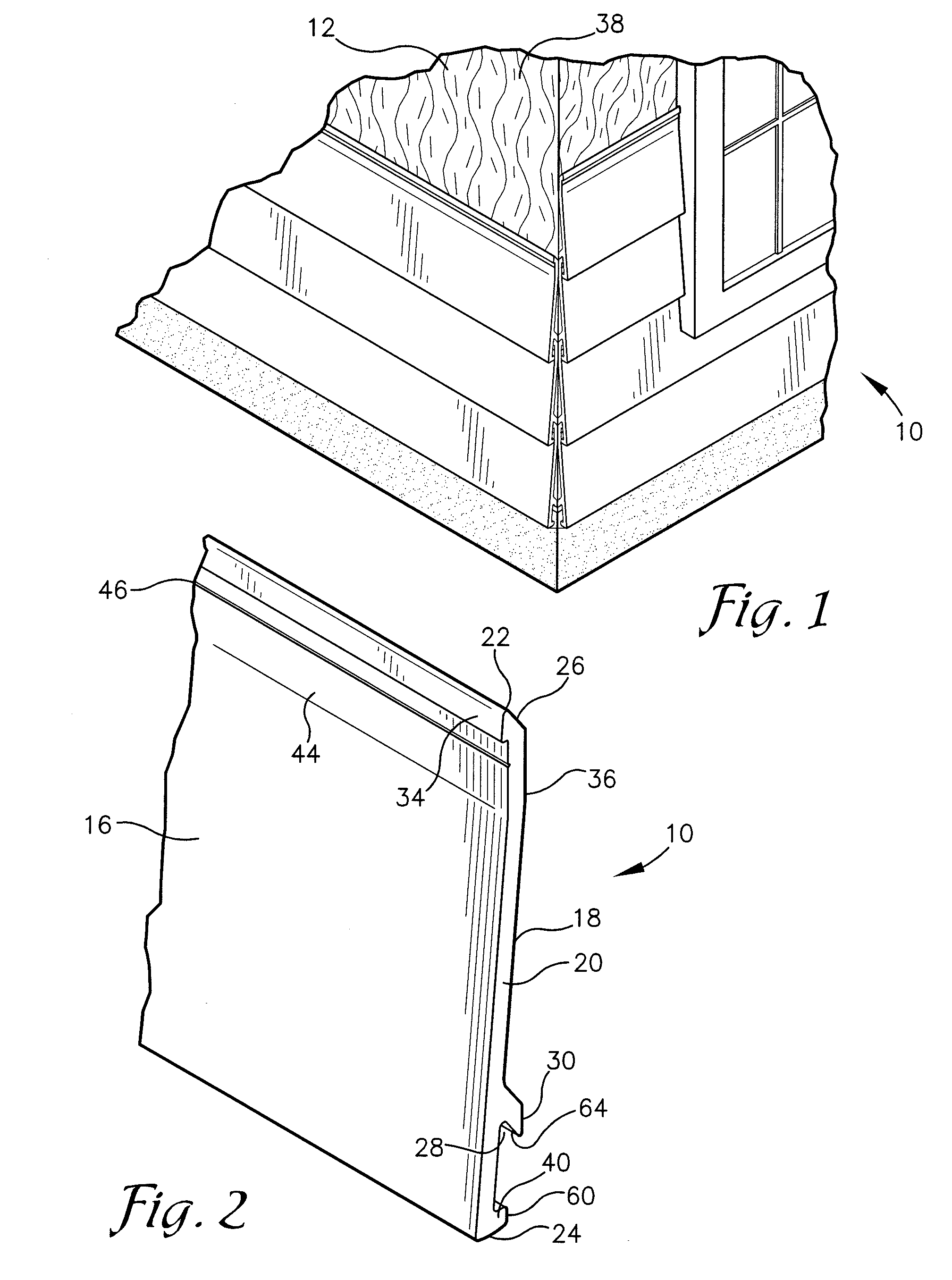
[0027]FIG. 1 illustrates a structure 12 with several courses of exterior siding panels 10 installed thereon. The siding panels 10 can be extruded in many different widths with 4 and 7 inches the industry preferred panel widths. The panels are installed beginning at the lowest level and courses are installed progressively higher until the desired portion of the wall 38 is covered. The panels 10 are preferably extruded using a polyvinyl chloride composition with organic and inorganic fillers that contribute to thermally stabilizing the panels so that when exposed to intense solar heat the panels do not substantially expand and contract causing problems with panel buckling and loosening of the nails that anchor the panels 10 to the building wall 38. The polyvinyl chloride in conjunction with the specially formulated organic and inorganic fillers produces a mechanically tough and resilient panel that is resistant to deformation from impacts such as hail and thrown objects as well as bei...


PUM


Abstract

Disclosed herein is an interlocking siding panel system for securing to the side of a structure with planar surfaces. When the panel is secured to the structure through the nail strip a full contact strip opposite the nail strip lays flat against the structure causing the panel portion below an point of inflection in the panel to raise up off of the structure creating a gap to facilitate movement of moisture past a locking leg that integrates with the panel below.

Description

FIELD OF THE INVENTION[0001]This disclosure pertains in general to a composite exterior siding panel that includes a system for interlocking panels that facilitate the downward movement of moisture away from the building structure. The disclosure also details how the system of interlocking panels limits the ability of wind to undermine the panels creating pressure differentials on the front and back surface that can dislodge the panel from the structure.BACKGROUND OF THE INVENTION[0002]Siding panels serve a two-fold objective of protecting a structure from damaging elements such as sunlight, moisture, hail and strong winds as well as providing an aesthetically appealing external appearance to the structure. The siding must be capable of protecting the structure from blisteringly hot sunlight that can induce thermal expansion and unattractive buckling of the siding. Siding produced from polyvinyl chloride (PVC) with organic and inorganic fillers has been shown to minimize thermal exp...

Claims


Application Information

Patent Timeline
IPC IPC(8): E04F13/21E04F13/26
CPCE04F13/0837E04F13/18E04F13/0864
Inventor DILONARDO, BRENT A.DICKEY, ERIC B.WADE, JOHN M.BAXTER, L. REX
Owner PLY GEM INDS
Why Eureka
Try Eureka