Vehicle seat side air bag system

a technology for side air bags and seat covers, which is applied in the direction of vehicular safety arrangements, pedestrian/occupant safety arrangements, vehicle components, etc., can solve the problems of air bag deployment, air bag deployment location variation, and air bag elasticity of covering materials and urethane foam padding, so as to resist elastic deformation of the trim cover

Inactive Publication Date: 2006-06-01
LEAR CORP
View PDF22 Cites 15 Cited by
  • Summary
  • Abstract
  • Description
  • Claims
  • Application Information

AI Technical Summary

Benefits of technology

[0009] According to one aspect of the present invention, a vehicle seat assembly is provided that comprises a frame and a pad formed of a shaped foam polymer material. The pad defines a pocket for receiving an air bag restraint sub-assembly and that is assembled to the frame. A restraint sub-assembly has a housing in which an air bag and an inflator are received. The housing has a split line that splits a wall of the housing. Upon inflation of the air bag by the inflator, the air bag is deployed through the split line. A trim cover is assembled to the pad and substantially encloses the frame, the pad and the restraint sub-assembly. The trim cover has a tear seam that opens when the air bag is deployed. At least one reinforcement panel extends partially around at least one side of the housing and between the housing and the trim cover. The reinforcement panel is held in engagement with the frame by a clip on a first edge of the reinforcement panel. The reinforcement panel is secured to the trim cover on a second edge at the tear seam. The reinforcement panel resists elastic deformation of the trim cover when the air bag is deployed and channels the air bag during deployment toward the tear seam.

Problems solved by technology

The elasticity of covering materials and urethane foam padding present a problem for air bag deployment.
This may increase air bag deployment time and result in variation in air bag deployment location.
The resiliency and tendency of the foam material to deform or fragment is another problem that must be solved.
The use of two panels complicates and assembly and may require that multiple pieces be joined together by seams.
In developing alternative designs to solve the problems associated with the Wu patent, other problems are presented that relate to assembling the air bag module to the seat with the force concentrator.
It is difficult to assemble the module to the seat frame, the concentrator and the seat cover.

Method used


Image

  • Vehicle seat side air bag system
  • Vehicle seat side air bag system
  • Vehicle seat side air bag system

Examples


Embodiment Construction

)

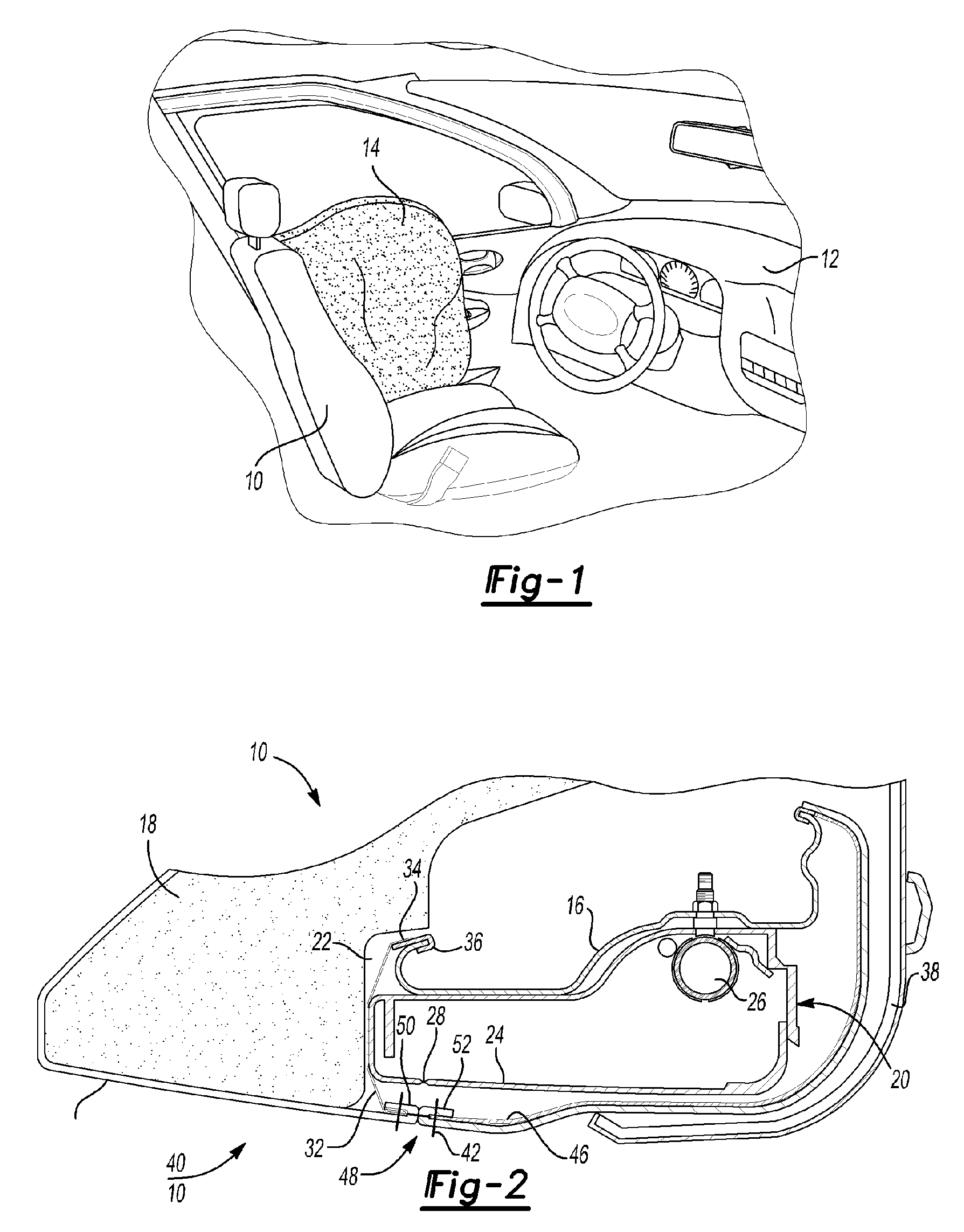
[0019] Referring now to FIG. 1, a seat 10 for vehicle 12 is shown with a side air bag 14 during deployment. The side air bag 14 is deployed in the event of a side impact to the vehicle 12. The side air bag 14 is deployed between the seat 10 and adjacent side of the vehicle 12 which is in most instances a vehicle door.

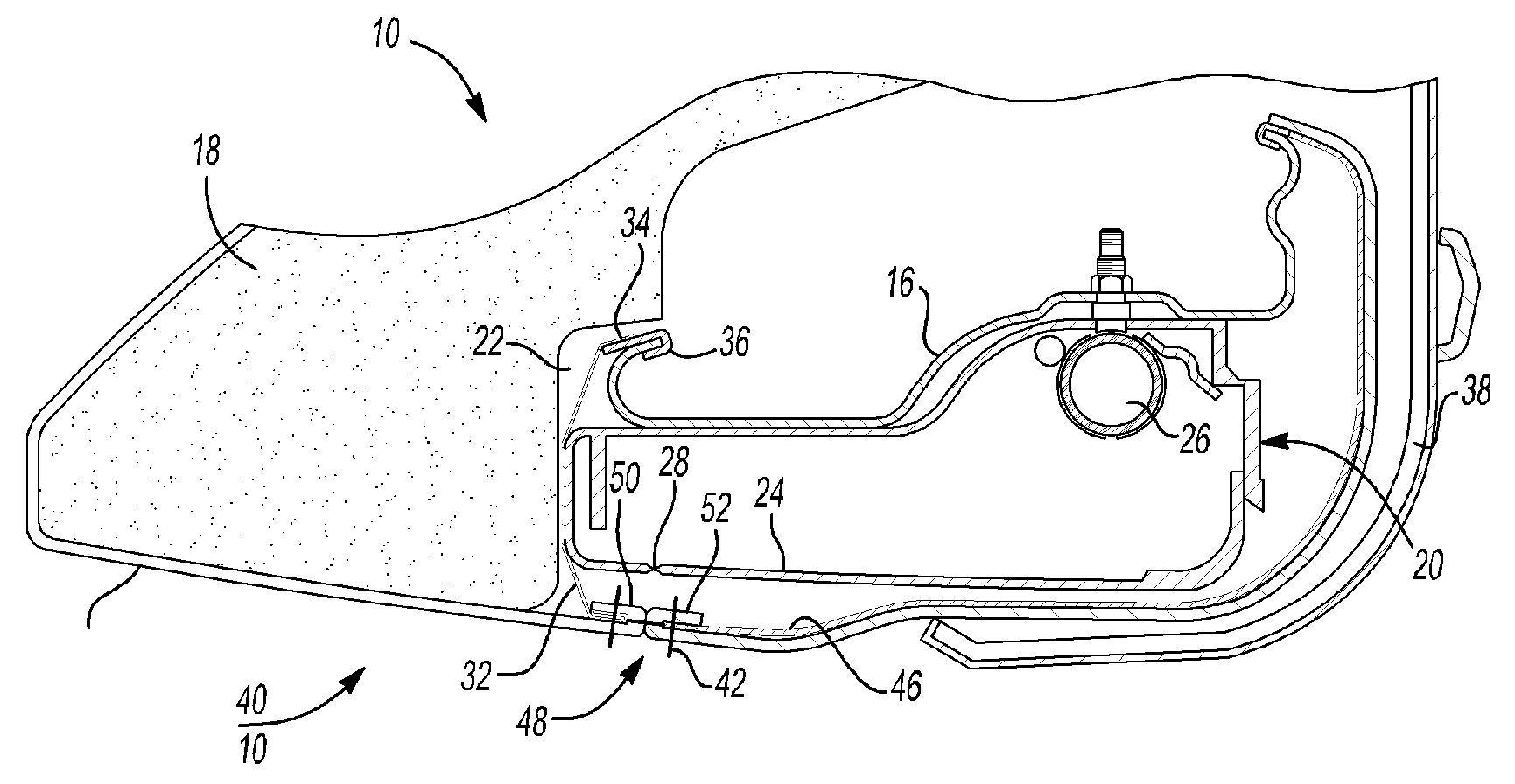
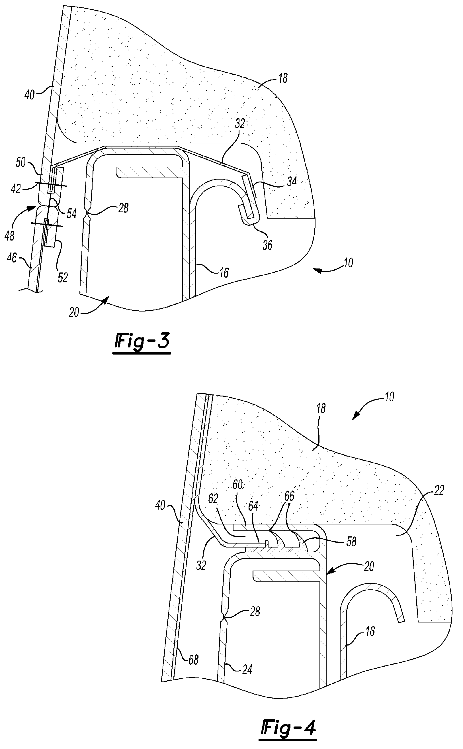
[0020] Referring to FIGS. 2 and 3, a portion of seat 10 is shown to include a frame 16 to which foam padding material comprising a foam pad 18 is secured. An air bag module 20 is received in a pocket 22 formed by the frame 16 and pad 18. The air bag module 20 has a housing 24 in which an inflator 26 is disposed. A folded air bag 14 is normally retained within the housing 24 that is inflated by the inflator 26. The housing 24 has a split line 28 and may be formed as a groove or perforation in the housing 24 that creates a stress riser in the housing so that the housing splits predictably at the split line 28.

[0021] A reinforcement panel 32 is secured at an anchoring e...


PUM


Abstract

A side air bag module is disposed in a cavity in a vehicle seat. At least one reinforcement panel is secured to either the air bag module or the seat frame on an anchoring edge. The opposite edge of the reinforcement panel is sewn to a hem on one side of a tear seam. A barbed retainer may be inserted in a slot to bear upon a peripheral flange portion of the air bag module.

Description

BACKGROUND OF THE INVENTION [0001] 1. Field of the Invention [0002] The present invention relates to a vehicle seat mounted side air bag restraint system. [0003] 2. Background Art [0004] Vehicle seat air bag restraint systems are used to protect vehicle occupants in the event of a side impact. To be effective, air bag restraint systems must deploy rapidly. Vehicle seats generally include a rigid frame to which foam pads are secured. The seat is enclosed within a cover made of vinyl, cloth or leather. Air bag modules are secured to the seat frame and generally include a housing, an air bag and an inflator system. [0005] The elasticity of covering materials and urethane foam padding present a problem for air bag deployment. As the air bag deploys, it must be channeled so that the air bag deploys through an air bag tear seam in the seat cover material. The elasticity of the seat cover material allows the air bag to expand and cause the seat cover material to bulge. This may increase ai...

Claims


Application Information

Patent Timeline
Patent Type & Authority Applications(United States)
IPC IPC(8): B60R21/22B60R21/00
CPCB60R21/207B60R2021/23146
Inventor TRACHT, MICHAEL L.DIERL, RICHARD G.USCHOLD, SEBASTIAN
Owner LEAR CORP
Why Eureka
Try Eureka