Multi-diaphragm pressure sensors

a pressure sensor and diaphragm technology, applied in the direction of fluid pressure measurement using elastically deformable gauges, instruments, mechanical elements, etc., can solve the problems of reducing the ability of sensors to return to normal operation, reducing the ability of pressure sensors reducing the difficulty of burst pressure ratio, etc., to achieve the effect of improving the ability to resist permanent deformation or fracture, reducing the risk of rupture, and improving the resistance to pressur

Inactive Publication Date: 2010-10-05
ORBITAL RES
View PDF18 Cites 15 Cited by
  • Summary
  • Abstract
  • Description
  • Claims
  • Application Information

AI Technical Summary

Benefits of technology

[0019]In a number of preferred embodiments, the sensor of the present invention comprises a substrate material with at least two openings, at least two flexible diaphragms provided on the substrate material over the at least two openings, and transducer elements deposited on, or in part comprising, the flexible diaphragms. The transducer elements are embedded or affixed above, under, or within the diaphragms, or include the diaphragms themselves as part of the transducers, and are electrically connected such that the signals are additive, providing a greater signal relative to the deflection of each diaphragm individually. The diaphragms of the present invention therefore can be made smaller, thicker, or less pliant such that they are better able to resist permanent deformation or fracture. The use of additive transduced signals of multiple diaphragms is especially useful where there is demand for very high overpressure capability relative to the pressure range of interest. The sensor design described gives the ability to precisely measure a small differential pressure across a valve, filter, etc. and still withstand the full pressure in a high-pressure system. A specific example is the ability to measure differential pressure across a control valve in the fire suppression systems of naval warships. The ability to achieve an operating range as small as a few pounds per square inch (psi) in a high pressure environment allows determination of the flow through the valve and can enable the ability to detect system leaks. The system itself runs at hundreds or thousands of psi, and both test and upset conditions can cause the differential pressure sensor to see the full system pressure, thus it is necessary to have a very high ratio of overpressure capability of the sensor relative to the measurement range of interest. Other systems that might benefit from a sensor such as this include (but are not limited to) nuclear power plants (both the radioactive side and the non-radioactive side), chemical plants, refineries, water distribution system, utility systems, engine control and the like.

Problems solved by technology

A diaphragm-type sensor is capable of returning to normal operation up to its maximum recovery pressure, even though it may deliver a saturated (i.e., constant, inaccurately low) output signal in the range between its maximum operating pressure and its maximum recovery pressure, such range being known as “overpressure.” Once the sensor exceeds its overpressure limit, the sensor may not be capable of returning to normal operation owing to a permanent deformation of the diaphragm or other structural or electrical damage resulting from the strain of the diaphragm beyond its elastic limits.
The burst pressure of a diaphragm-type sensor is the amount of pressure difference that can be placed across the diaphragm before it suffers a mechanical failure that results in leakage of fluid across the barrier created by the diaphragm.
The trade-off between diaphragm characteristics, e.g. opening size, thickness and stiffness, and burst pressure ratio is always a difficult challenge in the case of sensors that require high sensitivity in environments that may also present high maximum pressures.
A diaphragm-type sensor can be made to have a higher sensitivity by using a larger, thinner, more pliant diaphragm, as a greater range of mechanical deflection under strain is more easily transduced into a greater range of electrical signal output, but correspondingly these diaphragms are also more susceptible to fracturing under overpressure conditions, destroying the sensor.

Method used


Image

  • Multi-diaphragm pressure sensors
  • Multi-diaphragm pressure sensors
  • Multi-diaphragm pressure sensors

Examples


Embodiment Construction

)

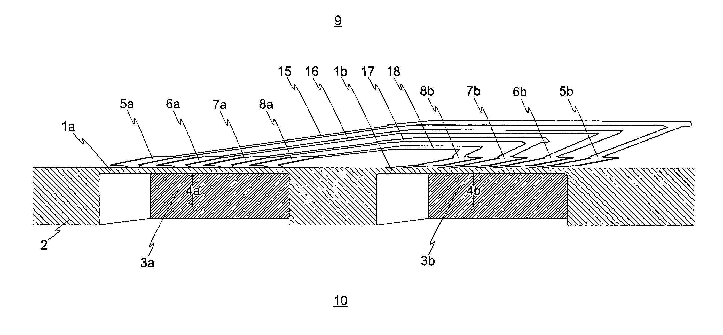
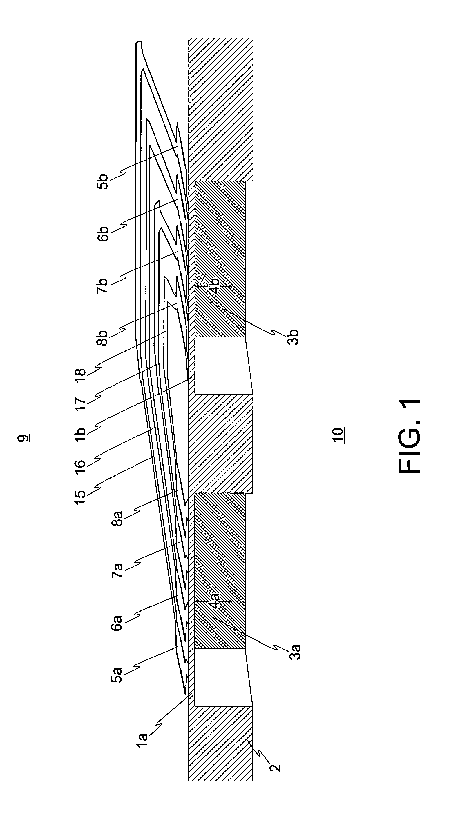
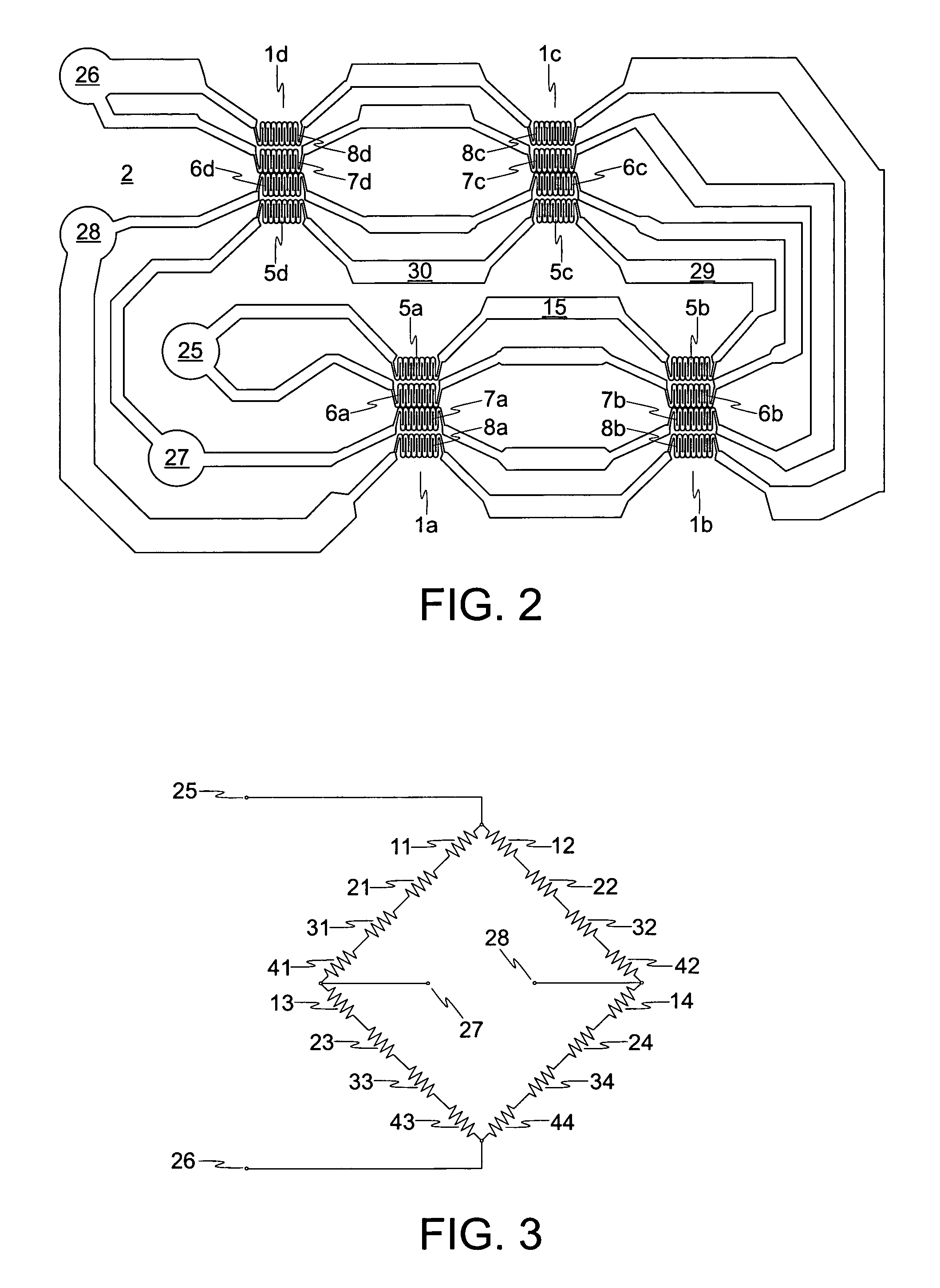
[0034]The present invention relates to pressure sensors that use multiple transducer elements to detect pressure-induced deflections of multiple flexible diaphragms, said transducer elements being wired in such a way that the signals are additive. The present invention further relates to pressure sensors of improved sensitivity. The present invention further relates to pressure sensors capable of sensing small pressure changes at high overall pressures. The present invention furthermore relates to multiple diaphragm pressure sensors wherein the individual diaphragms can be made smaller or stiffer to yield a higher burst pressure while retaining high sensitivity.

[0035]A number of embodiments of the present invention include a pressure sensor comprising a substrate with at least two openings and at least two flexible diaphragms held across the openings of the substrate. The substrate can be made from any material known to those skilled in the art. If the openings of the substrate are...


PUM

PropertyMeasurementUnit
pressureaaaaaaaaaa
pressuresaaaaaaaaaa
pressuresaaaaaaaaaa

Abstract

The present invention relates to a pressure sensor comprising multiple flexible diaphragms to which are affixed, within which are embedded, or which themselves constitute part of transducer elements that are connected together electrically, providing greater sensitivity and allowing the diaphragms to be made smaller, thereby increasing burst pressure to operating pressure ratio. This multi-diaphragm pressure sensor can therefore be used to accurately measure small changes in dynamic pressure in a fluid of overall high static pressure, for example, in a flow inventory control system as may be used in a fire suppression system, or for control of nuclear reactor systems.

Description

CROSS-REFERENCE TO RELATED APPLICATION[0001]This application claims the benefit of U.S. Provisional Application No. 60 / 933,264, filed Jun. 5, 2007.LICENSE RIGHTS-FEDERAL SPONSORED[0002]The U.S. Government has a paid-up license in this invention and the right in limited circumstances to require the patent owner to license others on reasonable terms provided for by the terms of contract numbers N65538-05-M0012 and N00024-06-C-4128 awarded by the United States Navy.BACKGROUND OF THE INVENTION[0003]1. Field of the Invention[0004]The present invention relates to sensors for measuring the pressure of fluids, and particularly to pressure sensors that involve the use of a diaphragm that is deflected by a pressure differential. More particularly, the invention relates to the use of multiple diaphragms to make a single pressure sensor with advantageous characteristics.[0005]2. Technical Background[0006]There exists a great need for the ability to precisely measure pressures of fluids (liquids...

Claims


Application Information

Patent Timeline
Patent Type & Authority Patents(United States)
IPC IPC(8): G01L7/08
CPCG01L9/0055G01L15/00G01L19/0618
Inventor SHAW, GREG S.
Owner ORBITAL RES
Why Eureka
Try Eureka