Base plate bearing device

A technology for carrying devices and substrates, which is applied in the direction of instruments, nonlinear optics, optics, etc., can solve the problems of substrate deformation and falling off, and achieve the effects of low deformation, solving deformation and falling off, and stable and firm fixation

Active Publication Date: 2016-05-11
BOE TECH GRP CO LTD +1
View PDF2 Cites 22 Cited by
  • Summary
  • Abstract
  • Description
  • Claims
  • Application Information

AI Technical Summary

Problems solved by technology

[0004] The technical problem to be solved by the present invention is: the traditional way of fixing the substrate with a clamper has the risk of substrate deformation and falling off, so it is necessary to provide a substrate carrying device that can increase the stability of substrate fixing

Method used


Image

  • Base plate bearing device
  • Base plate bearing device
  • Base plate bearing device

Examples


Embodiment 1

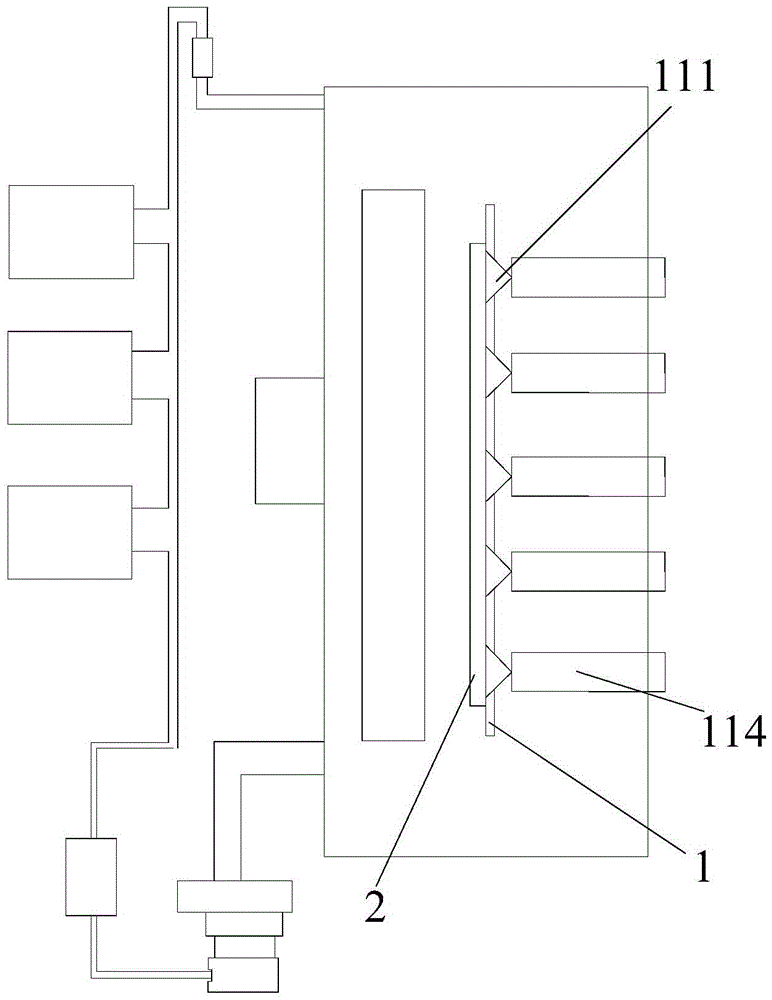
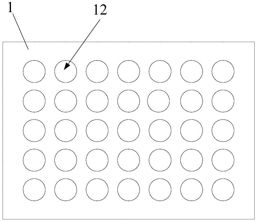
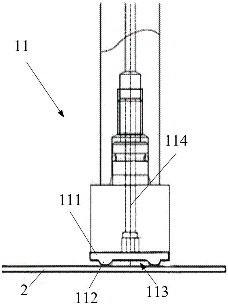
[0037] Such as figure 1 As shown, this embodiment provides a substrate carrying device, including a base 1 and a press-fit adsorption mechanism and a viscous adsorption mechanism arranged on the base 1. The press-fit adsorption mechanism is a vacuum adsorption component. , only the sputtering process is carried out in a vacuum state; for example, the vacuum adsorption can still be used to fix the substrate in the process of transportation, so in this embodiment, the vacuum adsorption assembly is used as the pressing mechanism, and the mechanical arm is used at the beginning. The substrate is placed on the base 1. At this time, the vacuum adsorption component adsorbs and fixes the substrate on the base 1, and at the same time makes the substrate press the viscous adsorption mechanism. At this time, the vacuum adsorption mechanism and the viscous adsorption work at the same time. The substrate is adsorbed; of course, the vacuum adsorption mechanism can also stop working after pr...

Embodiment 2

[0041] Such as Figure 4 As shown, this embodiment provides a substrate carrying device, including a base 1 and a press-fit adsorption mechanism and a viscous adsorption mechanism arranged on the base 1. The press-fit adsorption mechanism is a vacuum adsorption component. In the sputtering process, only the sputtering process is carried out in a vacuum state; for example, the vacuum adsorption can still be used to fix the substrate in the process of transportation, so in this embodiment, the vacuum adsorption assembly is also used as the pressing mechanism. The robotic arm places the substrate on the base 1. At this time, the vacuum adsorption component adsorbs and fixes the substrate on the base 1. At the same time, the substrate is pressed against the viscous adsorption mechanism. At this time, the vacuum adsorption mechanism and the viscous adsorption are simultaneously work together to adsorb the substrate; of course, it is also possible that the vacuum adsorption mechanis...

Embodiment 3

[0045] Such as Figure 5 As shown, the substrate carrying device provided in this embodiment includes a base 1 and a press-fit adsorption mechanism and a viscous adsorption mechanism disposed on the base 1, wherein the viscous adsorption mechanism is a second viscous adsorption mechanism disposed on the base 1. Adsorption layer 14, the press-fit adsorption mechanism is an electrostatic adsorption layer 141 arranged between the base 1 and the second viscous adsorption layer 14; the original vacuum adsorption mechanism is replaced by setting the electrostatic adsorption layer 141, optionally, The electrostatic adsorption layer 141 is made of a metal electrode material; its principle is that the metal electrode is energized, and due to the phenomenon of electrostatic induction, the end close to the metal electrode induces a charge opposite to that of the metal electrode, and is attracted and attached to the metal electrode. ; During use, the electrostatic adsorption layer 141 app...


PUM


Abstract

The invention relates to the technical field of liquid crystal display design and manufacturing, in particular to a base plate bearing device which comprises a base platform, a press fit sucking mechanism and an adhesive sucking mechanism, wherein the press fit sucking mechanism and the adhesive sucking mechanism are arranged on the base platform; the adhesive sucking mechanism is made of an adhesive material; the press fit sucking mechanism is used for enabling the base plate to be tightly pressed to the adhesive sucking mechanism. When being placed on the base platform by using a manipulator, the base plate can be sucked by the adhesive sucking mechanism made of the adhesive material through action force of molecules, and can be fixed on the base platform, so that the problems that the base plate can be deformed and is relatively poor in coating uniformity when being fixed by using a clamp are solved; compared with a conventional fixation mode of a triangular clamp, the base plate bearing device is relatively stable and solid, the deformation quantity of the base plate is relatively low, the coating uniformity is greatly improved, and meanwhile the defects that the base plate is deformed and dropped are also solved.

Description

technical field [0001] The invention relates to the technical field of liquid crystal display design and manufacture, in particular to a substrate carrying device. Background technique [0002] At present, in the field of liquid crystal displays, a vertical sputtering method is generally used for sputtering substrates, which saves operating space and has a fast sputtering speed. However, the current glass substrates are ultra-thin substrates, only 0.5mm or even 0.4 or 0.3mm. Since the glass substrate is very thin, and the sputtering chamber is in a vacuum state during sputtering of the substrate, vacuum adsorption cannot be used; currently The carrying device used to transport the substrate mainly uses clamps to clamp the glass substrate in the device. However, the use of clamps to fix the substrate on the carrying device is prone to deformation of the substrate, which makes the uniformity of the coating on the substrate poor and affects the quality of the substrate. Qualit...

Claims


Application Information

Patent Timeline
Patent Type & Authority Applications(China)
IPC IPC(8): G02F1/13
CPCG02F1/1303
Inventor 井杨坤
Owner BOE TECH GRP CO LTD
Why Eureka
Try Eureka