Hydrodynamic foil face seal

a foil face seal and hydrodynamic technology, applied in the direction of sliding contact bearings, mechanical equipment, machines/engines, etc., can solve the problems of insufficient differential pressure to separate the seal face, failure to achieve hydrostatic seals, and inability to use hydrostatic seals

Inactive Publication Date: 2007-08-28
R & D DYNAMICS CORPORATION
View PDF25 Cites 36 Cited by
  • Summary
  • Abstract
  • Description
  • Claims
  • Application Information

AI Technical Summary

Benefits of technology

[0021]Optionally, the top plate may comprise a low-friction, low-wear surface.

Problems solved by technology

Where this cannot be guaranteed, such as inside a gas turbine engine, success has proved elusive.
During engine start and shutdown, differential pressure is sometimes insufficient to separate the seal faces.
Although promising for some gas turbine applications, hydrostatic seals cannot be utilized when the surface speed is high, typically over 305 meters / second (m / s) (1000 ft / s).

Method used


Image

  • Hydrodynamic foil face seal
  • Hydrodynamic foil face seal
  • Hydrodynamic foil face seal

Examples


Embodiment Construction

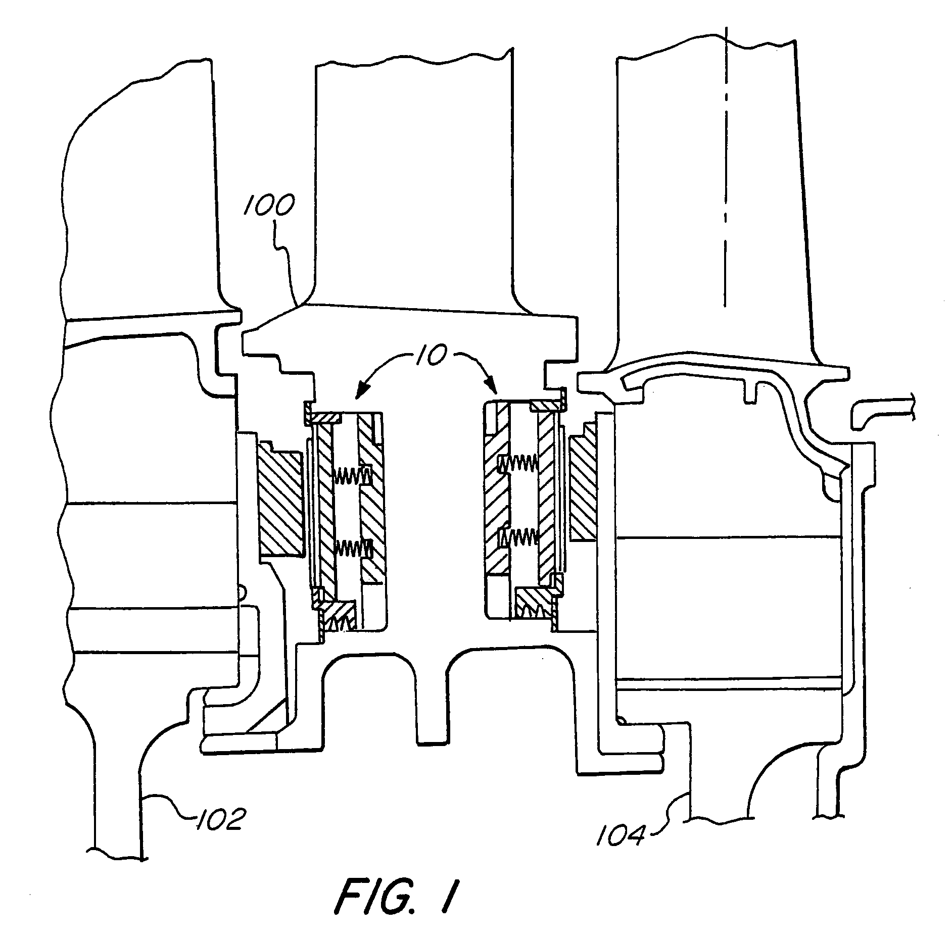
[0027]Gas film riding seals have found wide acceptance in pipeline and process industry turbomachinery. However, such seals have not found utility in gas turbine prime movers.

[0028]The gas turbine operating environment requires that the seals operate at relatively high surface velocities and higher temperatures than those of all other applications, and flight-worthy gas turbines must meet additional restrictions on the allowable size and weight of the seal. Furthermore, the structural portions of an aircraft engine are lightweight, which means that the seal cannot be completely isolated from the distortion of the surrounding structure. It is this last problem which more than anything else has prevented the use of film-riding bearings in gas turbine aircraft engines.

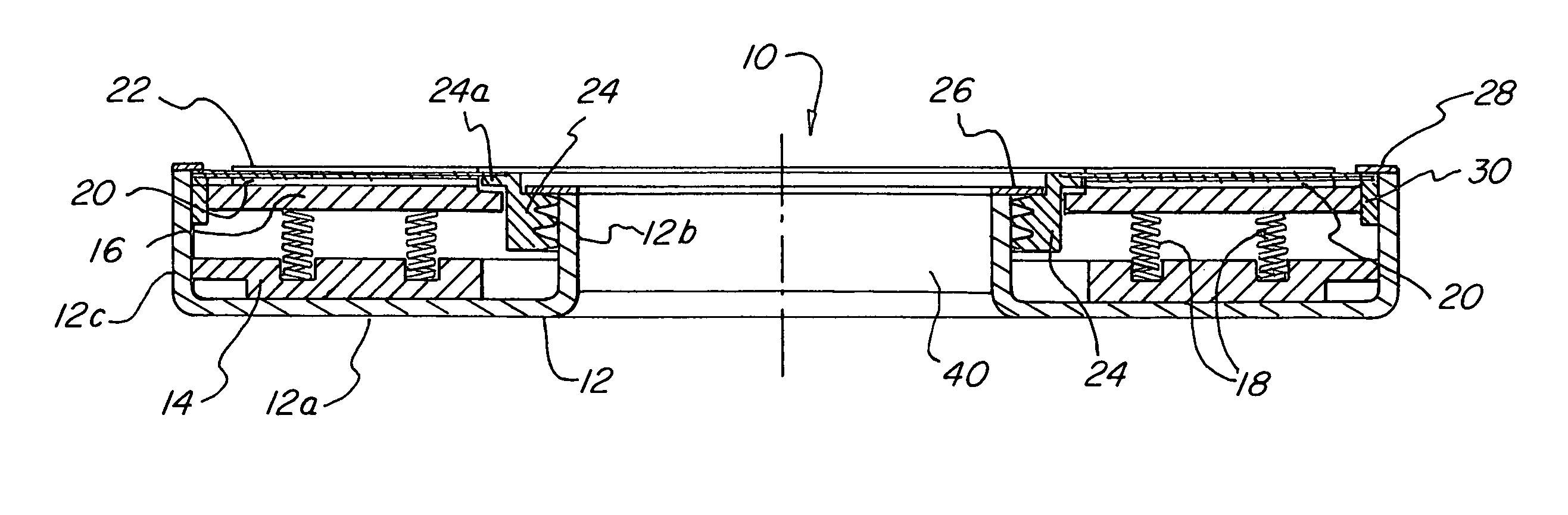
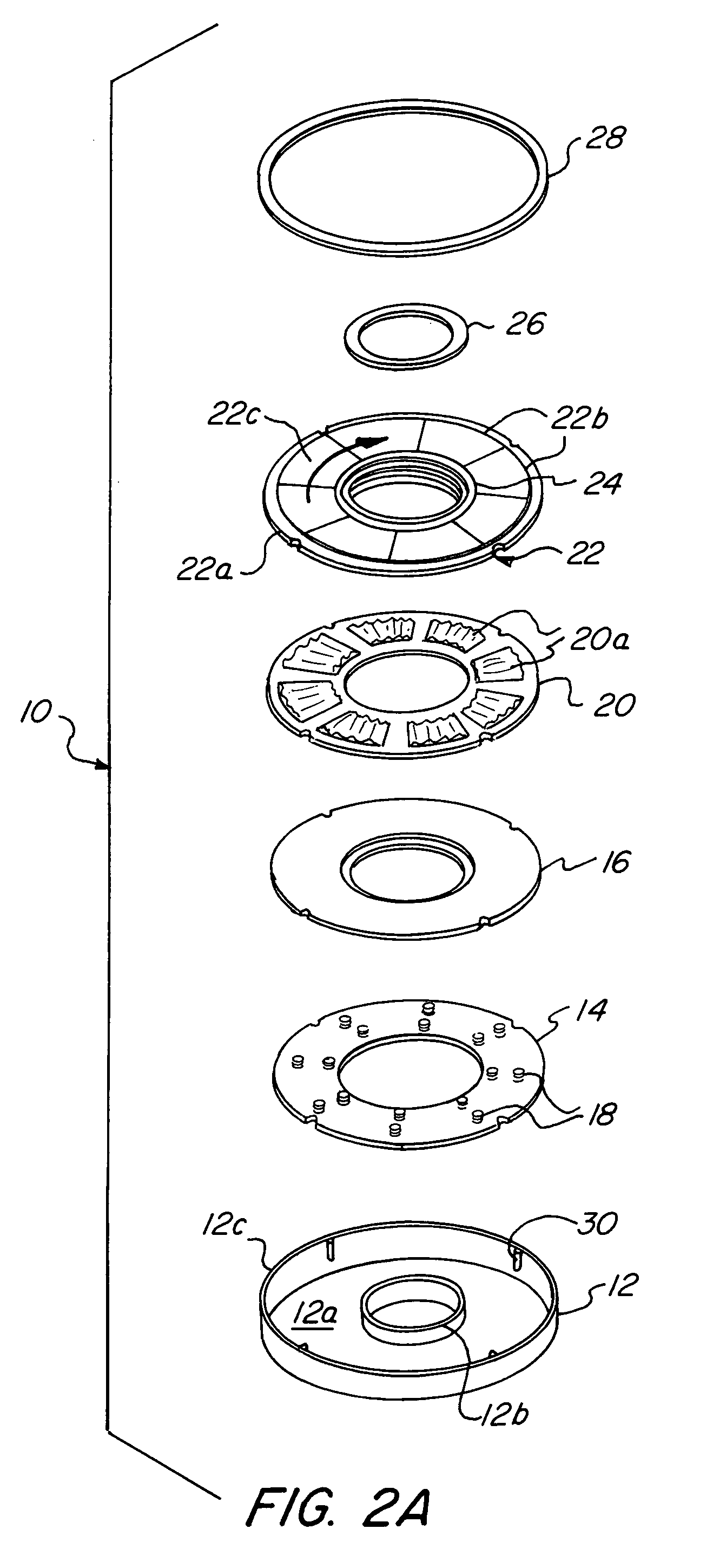
[0029]This invention provides a hydrodynamic foil face seal that is much better than prior art devices at accommodating axial excursions, misalignments, out-of-flatness, conical distortion and circumferential distortion. ...


PUM


Abstract

A foil thrust bearing forms the primary rotating interface for a film riding face seal. This face seal includes a spring system that will allow the entire assembly to translate axially relative to a static attachment. The complete assembly will form a hybrid foil / film riding face seal that shows much promise at being sufficiently flexible to enable operation in a gas turbine engine. The seal includes a flexible top plate having a non-flat surface under its working conditions, and a spring support system to allow the top plate to accommodate axial excursions and out-of-flat distortions.

Description

CROSS-REFERENCE TO RELATED APPLICATIONS[0001]This application claims the benefit of U.S. Provisional Application Ser. No. 60 / 303,588, filed Jul. 6, 2001.BACKGROUND OF THE INVENTION[0002]1. Field of the Invention[0003]This invention pertains to the field of gas riding face seals.[0004]Gas turbine engines bleed off some of the compressed air from the primary gas path into so-called secondary flow circuits for various reasons, mainly to cool various components within the engine. This withdrawal of air is a parasitic loss to the engine thermodynamic cycle causing degradation in efficiency.[0005]Secondary airflows are metered via air-to-air seals that are typically placed at interstage locations in the turbine engine. Relative velocities are high, typically about 150 meters / second (about 500 ft / sec) and up, and temperatures in the turbine section of the engine of about 425° C. (about 800° F.) and greater are typical. Since the beginning of the gas turbine, labyrinth seals have traditiona...

Claims


Application Information

Patent Timeline
Patent Type & Authority Patents(United States)
IPC IPC(8): F16J15/34F16C32/06F16C17/12
CPCF16C17/042F16J15/3432F16C2360/23
Inventor AGRAWAL, GIRIDHARI L.PATEL, KIRTIKUMAR H.MUNSON, JOHN H.
Owner R & D DYNAMICS CORPORATION
Why Eureka
Try Eureka