

Swing aeroelastic model and shock-test wind tunnel test method thereby
A technology of aeroelastic model and rigid model, which is applied in the field of wind resistance design test of construction engineering structure, can solve the problems that the test accuracy cannot be guaranteed, and achieve the effects of low cost, accurate test results, accurate stiffness and quality
Active Publication Date: 2013-01-02
FOSHAN POWER SUPPLY BUREAU GUANGDONG POWER GRID +1
View PDF5 Cites 25 Cited by
- Summary
- Abstract
- Description
- Claims
- Application Information
AI Technical Summary
Problems solved by technology
[0008] Based on this, the present invention is to overcome the defects in the prior art that the vibrations of each axial direction of the pendulous aeroelastic model are coupled to e
Method used
View moreImage
Smart ImageViewing Examples

Examples
 PUM
 Abstract
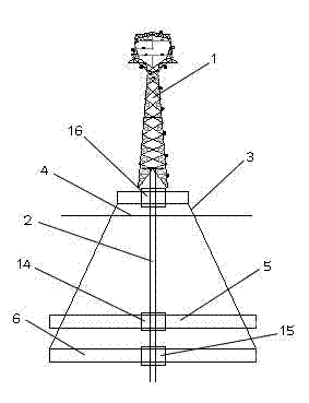
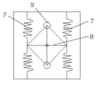
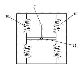
The invention discloses a swing aeroelastic model and a shock-test wind tunnel test method thereby and belongs to the technical field of structural wind-resistant design and test for building engineering. The swing aeroelastic model comprises a high-rise building rigid model, a rigid support rod and a support. The high-rise building rigid model is disposed at the upper end of the rigid support rod which is disposed vertically and is located above the support. The swing aeroelastic model further comprises a torsional vibration layer, an X-axial vibration layer and a Y-axial vibration layer, which are horizontally disposed on the support. The rigid support rod is connected with and penetrates through the vibration layers. The shock-test wind tunnel test method by the swing aeroelastic model includes the steps of firstly, setting the swing aeroelastic model; secondly, respectively regulating rigidity of springs and mass of mass blocks in the torsional vibration layer, the X-axial vibration layer and the Y-axial vibration layer according to test requirements so as to meet the test requirements; and thirdly, setting the swing aeroelastic model meeting the test requirements in a wind field, and performing wind tunnel test. Axial vibrations are not coupled, and more accurate test results can be obtained.
Description
[0001] technical field [0002] The invention relates to a wind-resistant design test technology for building engineering structures, in particular to a pendulum aeroelastic model for wind tunnel tests and a seismic wind tunnel test method for the aeroelastic model. [0003] Background technique [0004] In recent years, with the increase of building height and the use of lightweight and high-strength materials, the wind-induced response of high-rise buildings has become more and more significant. Therefore, the requirements for structural wind-resistant design are very high, and its aeroelastic effect must be accurately grasped. [0005] As a kind of high-rise building, the transmission tower is a typical wind-sensitive structure, and accidents of falling towers and breaking wires under the action of wind loads often occur. As an important carrier of power transmission, the safety of transmission towers is an important guarantee for the sound and rapid development of my co...
Claims
Login to View More Application Information
Patent Timeline
 IPC IPC(8): G01M9/08G01M9/06
Inventor何山武利会杨国斌郑金杯刘高张虎刘宝强樊友平
OwnerFOSHAN POWER SUPPLY BUREAU GUANGDONG POWER GRID