Vibration cutting apparatus

A technology of cutting device and cutting edge, which is applied in metal processing and other directions, and can solve the problems of cutting edge 802 falling off, embedding, brazing material or solder damage, etc.

Active Publication Date: 2013-01-02
ADWELDS CORP
View PDF12 Cites 7 Cited by
  • Summary
  • Abstract
  • Description
  • Claims
  • Application Information

AI Technical Summary

Problems solved by technology

[0016] In this way, a stress with a large difference in magnitude between the central portion and both end portions in the width direction is generated at the bonding portion between the cutting blade 802 and the resonator 800, and there is a problem that the bonding of the cutting blade 802 and the resonator 800 is difficult. Partial damage to the solder or solder, or worst case, the cutting edge 802 falls of

Method used


Image

  • Vibration cutting apparatus
  • Vibration cutting apparatus
  • Vibration cutting apparatus

Examples


no. 1 approach

[0105] refer to Figure 1 to Figure 6 , the first embodiment of the vibration cutting device of the present invention will be described.

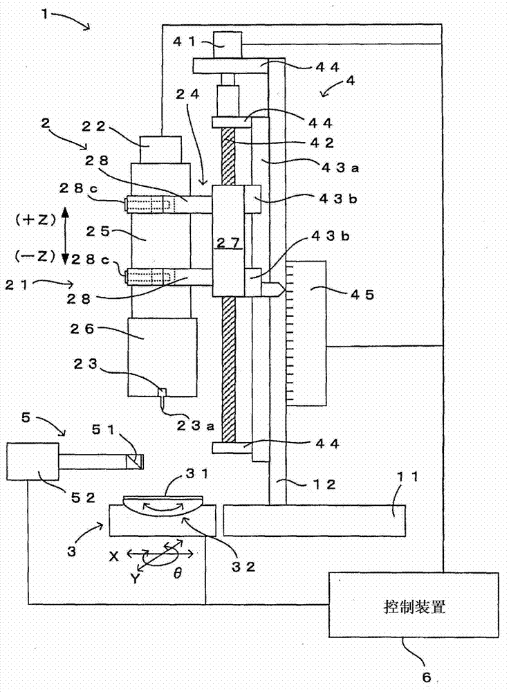
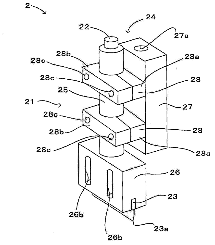
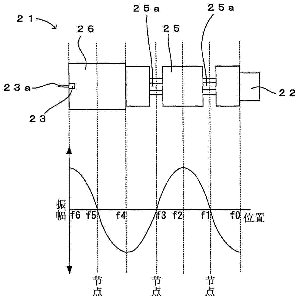
[0106] figure 1 It is the figure which looked at the 1st Embodiment of the vibration cutting apparatus 1 of this invention from the side. figure 2 will be figure 1 A three-dimensional view obtained by enlarging the main part of . image 3 yes means figure 1 A diagram of the resonator 21. Figure 4 It is an enlarged view of a state in which the honing head 26 constituting the resonator 21 is turned upside down, (a) is a perspective view, (b) is a side view, and (c) is a front view. Figure 5 yes image 3 The shown resonator 21 is supported by the support mechanism 24 and is formed in a horizontal state, (a) is a side view, and (b) is a cross-sectional view taken along line A-A of (a). Figure 6 yes means figure 1 A flow chart of an example of the operation.

[0107] (device structure)

[0108] figure 1 The vibration cutting ...

no. 2 approach

[0167] refer to Figure 10 , the second embodiment of the vibration cutting device of the present invention will be described. Figure 10 It is a figure which shows the resonator 321 of 2nd Embodiment of the vibration cutting apparatus 1 of this invention. Such as Figure 10 As shown, the difference between the resonator 321 of this embodiment and the resonator 21 of the above-mentioned first embodiment is that the side surface of the honing head 326 included in the resonator 321 is penetratingly provided with The long hole 326b. The other configurations and actions are the same as those of the above-mentioned first embodiment. Therefore, the following description will focus on the differences from the first embodiment. For the same configurations and actions as those of the above-mentioned embodiment, the same reference numerals will be used to omit them. Description of structure and action.

[0168] Such as Figure 10 As shown, the resonator 321 in this embodiment inclu...

no. 3 approach

[0172] refer to Figure 11 , the third embodiment of the vibration cutting device of the present invention will be described. Figure 11 It is an enlarged view of main parts of the honing head 26 and the stand 3 of the third embodiment of the vibration cutting device 1 of the present invention, and (a) to (c) show different states, respectively. Such as Figure 11 As shown in (a) to (c), the stand 3 of this embodiment is different from the stand 3 of the above-mentioned first embodiment in that the stand 3 is equipped with a buffer layer 33, and the buffer layer 33 is provided with a space for placing the object to be cut. The loading surface 31a. The other configurations and actions are the same as those of the above-mentioned first embodiment. Therefore, the following description will focus on the differences from the first embodiment. For the same configurations and actions as those of the above-mentioned embodiment, the same reference numerals will be used to omit them. ...


PUM


Abstract

Provided is a technique which can prevent abnormal vibrations from occurring on a resonator and apply, to a cutting edge, vibrations with the magnitude of amplitude thereof adjusted in the direction of width of the edge, thereby cutting an object of interest with high accuracy. The resonator (21) with a grip portion grasped with clamp means (28) is supported by a support means (24), thereby preventing abnormal vibrations from occurring on the resonator (21). The resonator (21) has at least one elongated hole (26b) defined through a side thereof, thus allowing for adjusting the amplitude magnitude of vibrations in the direction of width of the cutting edge (23) on one end of the resonator (21). This enables vibrations with the amplitude of an adjusted magnitude in the direction of width to be applied to the cutting edge (23). Accordingly, the cutting edge (23) which is adequately vibrated can be used to cut the object of interest with high accuracy.

Description

technical field [0001] The present invention relates to a technique for cutting an object by applying vibration to a flat cutting blade having a cutting edge formed on one end thereof. Background technique [0002] Conventionally, there is known a technique for cutting an object by applying vibration to a flat plate-shaped cutting blade having a cutting edge formed on one end side (for example, refer to Patent Document 1). That is, a vibrator is connected to one end of the resonator, and a cutting blade is attached to the other end of the resonator that resonates with the vibration generated by the vibrator. Cutting the object of the ceramic green sheet prevents the cutting edge from bending when the object is cut, and obtains a cut sheet with a better cut surface than when no vibration is applied to the cutting edge. [0003] prior art literature [0004] patent documents [0005] Patent Document 1: Japanese Patent Application Laid-Open No. 1-122408 (upper right column o...

Claims


Application Information

Patent Timeline
IPC IPC(8): B26D7/08B26D1/08B26D7/20
CPCB26F1/40B26D7/086B26D1/0006B26D7/2614B26D3/085Y10T83/8804B26D1/08B26D7/08B26D7/20
Inventor 中居诚也野田和宏平间正一
Owner ADWELDS CORP
Why Eureka
Try Eureka