Passenger conveyor device
Technology of a passenger conveyor, conveyor chain, used in the direction of transport and packaging, escalators
- Summary
- Abstract
- Description
- Claims
- Application Information
AI Technical Summary
Problems solved by technology
Method used
Image
Examples
no. 1 Embodiment approach
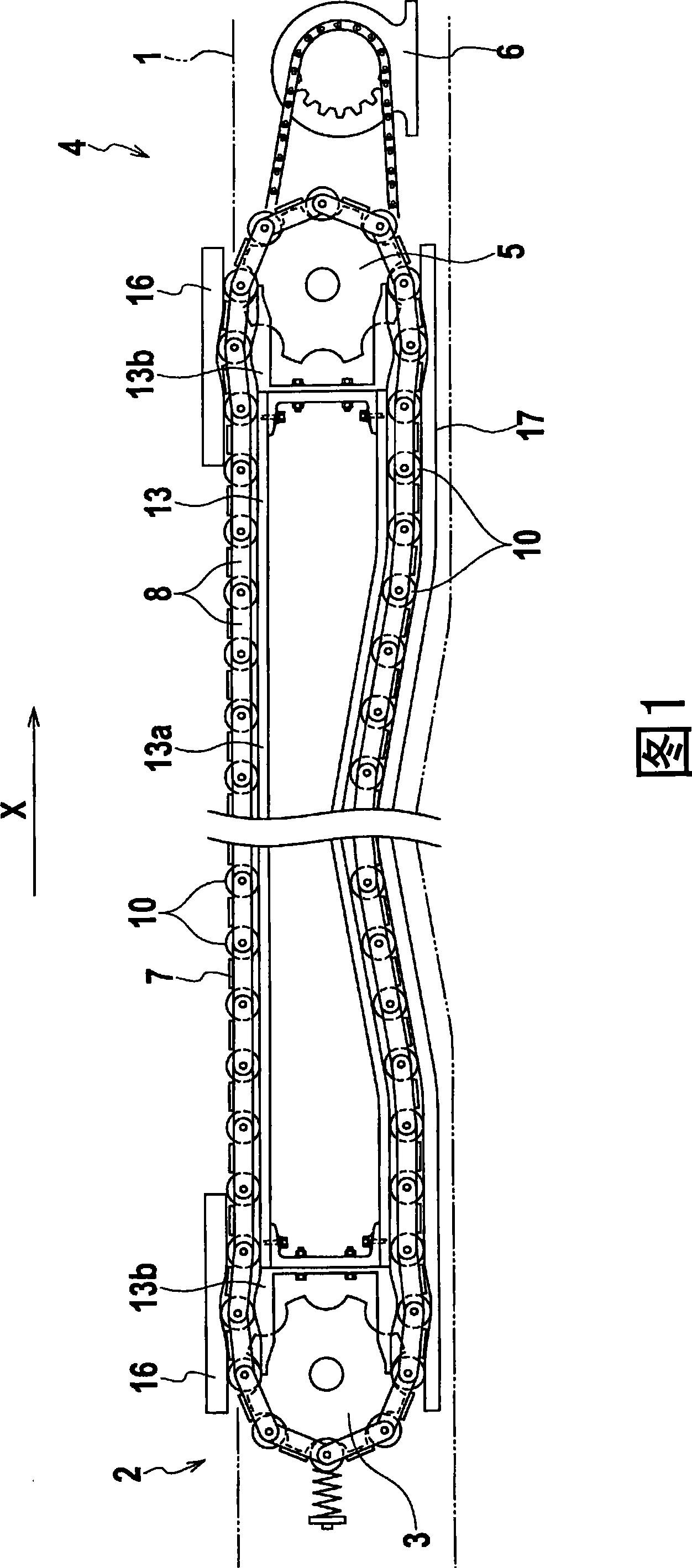
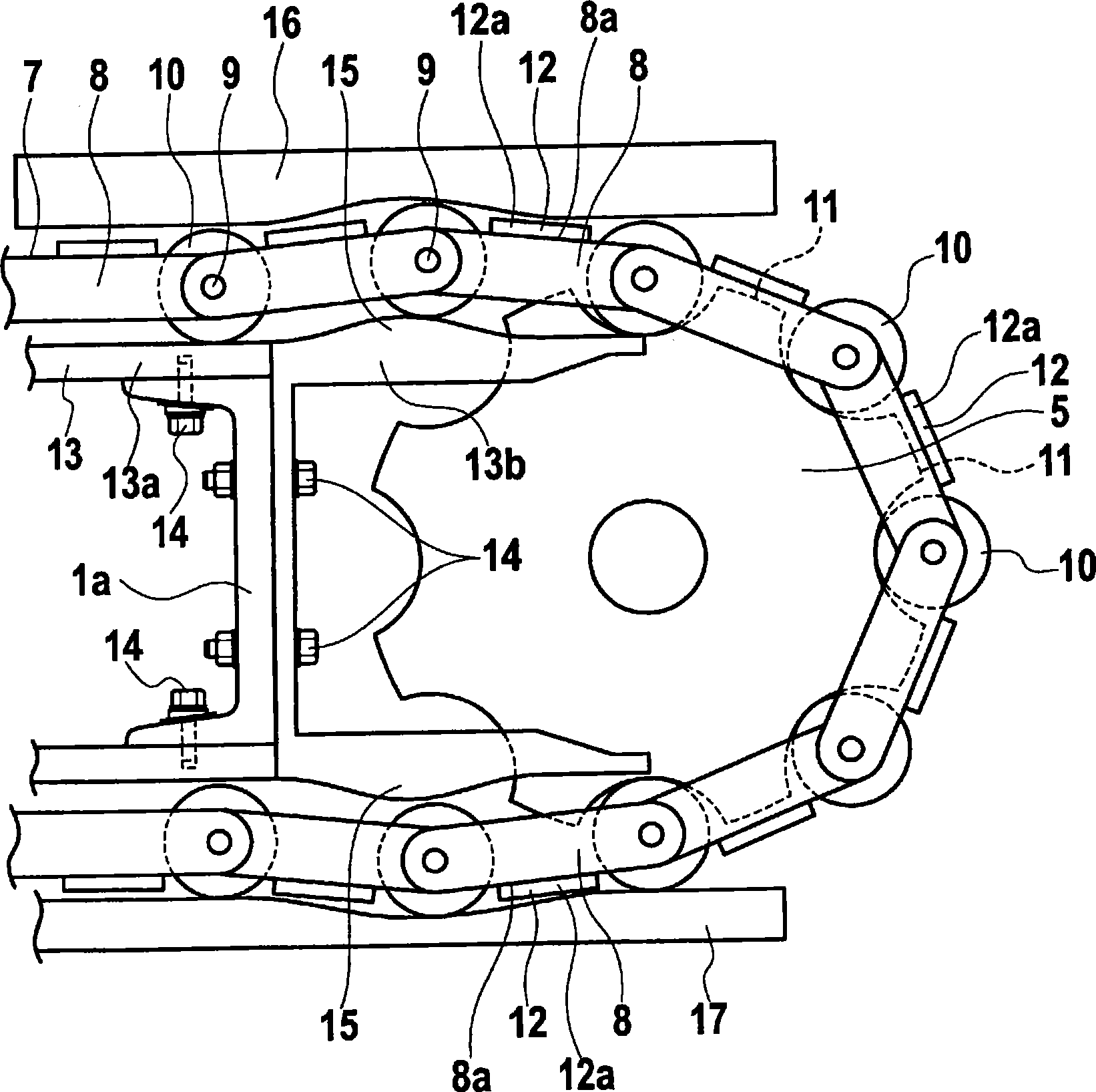
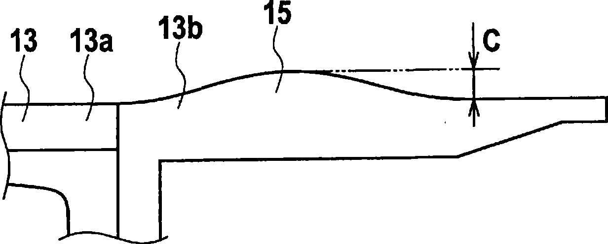
[0030] Such as figure 1 As shown, the moving walk as the passenger conveyor device according to the first embodiment of the present invention has a truss 1 provided in the horizontal direction. The truss 1 is accommodated in a concave-shaped pit formed on the lower side of the road surface. In the truss 1, a pair of driven-side sprockets 3 on the inlet 2 side, a pair of driving-side sprockets 5 on the outlet 4 side, and a structure for transmitting the driving force to the driving-side sprockets 5 are disposed. Rotary drive 6.
[0031] An endless conveyor chain 7 is stretched between the driving side sprocket 5 and the driven side sprocket 3 . In addition, there are two conveyor chains 7, and one conveyor chain 7 is erected between a group of sprockets 3,5. Furthermore, another conveyor chain 7 is stretched between another set of sprockets 3 , 5 . The two groups of sprockets 3 and 5 and the two conveyor chains 7 are arranged in parallel positions in the horizontal directi...
no. 2 Embodiment approach
[0045] based on Figure 5 A second embodiment of the present invention will be described. In addition, in the second embodiment and subsequent embodiments, the same components as those described in the first embodiment are denoted by the same reference numerals, and overlapping descriptions are omitted.
[0046] In the moving walk as the passenger conveyor device according to the second embodiment, a pair of sprockets 3, 5 (refer to figure 1 ) An endless conveyor chain 7A is erected between.
[0047] The conveyor chain 7A includes a plurality of link plates 21 positioned parallel to each other and a set of two, and a plurality of connection shafts 9 connecting end portions of the link plates 21 to each other. On the connecting shaft 9, the wheel 10 which is located between the chain plate 21 which is a set of two and which also serves as a conveying roller and a guide roller is attached.
[0048] Two conveyor chains 7A are arranged in parallel positions in the horizontal d...
no. 3 Embodiment approach
[0054] refer to Figure 6 A third embodiment of the present invention will be described.
[0055] In the moving walk that is the passenger conveyor device according to the third embodiment, the guide rail 31 arranged along the circular movement direction of the conveyor chain 7 is provided in the truss 1 . The guide rail 31 is composed of a single central guide rail 31a and two end guide rails 31b. Furthermore, the end part guide rail 31b is fixed to the both ends of the center part guide rail 31a with a bolt. On the end guide rails 31b which are a part of the guide rails 31, two bent portions 15 formed protruding in a mountain shape toward the outer peripheral side of the circular movement path of the conveyor chain 7 are provided each. In the guide rail 31 , in the front and rear regions sandwiching the curved portion 15 , the heights from the respective regions to the top of the curved portion 15 are set to be different. For example, the height "I" to the top of the curv...
PUM
 Abstract
Description
Claims
Application Information
 - R&D
- Intellectual Property
- Life Sciences
- Materials
- Tech Scout
- Unparalleled Data Quality
- Higher Quality Content
- 60% Fewer Hallucinations
Browse by: Latest US Patents, China's latest patents, Technical Efficacy Thesaurus, Application Domain, Technology Topic, Popular Technical Reports.
© 2025 PatSnap. All rights reserved.Legal|Privacy policy|Modern Slavery Act Transparency Statement|Sitemap|About US| Contact US: help@patsnap.com


