Passenger conveyor device

A technology of passenger conveyors and conveyor chains, applied in transportation, packaging, escalators, etc., can solve problems such as failure to achieve gap size, and achieve the effect of preventing abnormal vibration and noise

Inactive Publication Date: 2009-05-06
TOSHIBA ELEVATOR KK
View PDF4 Cites 0 Cited by
  • Summary
  • Abstract
  • Description
  • Claims
  • Application Information

AI Technical Summary

Problems solved by technology

[0014] Therefore, reducing the size of the gap between the guide rail and the pressure rail to the outer diameter of the guide roller has not been achieved

Method used


Image

  • Passenger conveyor device
  • Passenger conveyor device
  • Passenger conveyor device

Examples


no. 1 Embodiment approach

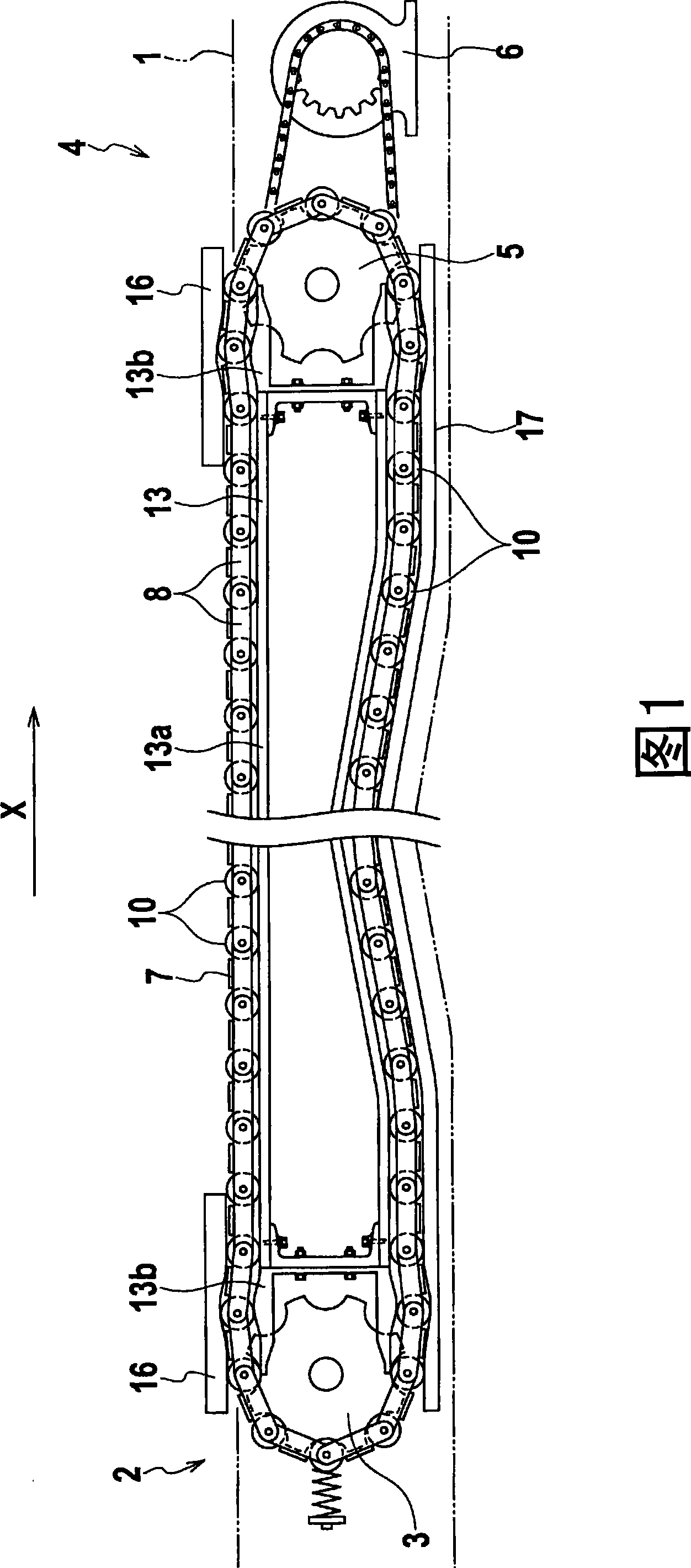
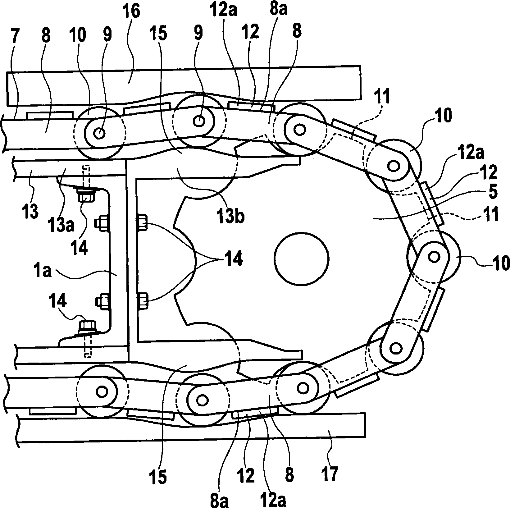
[0027] As shown in FIG. 1 , as a moving walkway of a passenger conveyor device according to a first embodiment of the present invention, a truss 1 provided in the horizontal direction is provided. The truss 1 is accommodated in a concave-shaped pit formed on the lower side of the road surface. In the truss 1, a pair of driven-side sprockets 3 on the inlet 2 side, a pair of driving-side sprockets 5 on the outlet 4 side, and a structure for transmitting the driving force to the driving-side sprockets 5 are disposed. Rotary drive 6.

[0028] An endless conveyor chain 7 is stretched between the driving side sprocket 5 and the driven side sprocket 3 . In addition, there are two conveyor chains 7, and one conveyor chain 7 is erected between a group of sprockets 3,5. Furthermore, another conveyor chain 7 is stretched between another set of sprockets 3 , 5 . The two groups of sprockets 3 and 5 and the two conveyor chains 7 are arranged in parallel positions in the horizontal direct...

no. 2 Embodiment approach

[0042] based on Figure 5 A second embodiment of the present invention will be described. In addition, in the second embodiment and subsequent embodiments, the same components as those described in the first embodiment are denoted by the same reference numerals, and overlapping descriptions are omitted.

[0043] In the moving walk that is the passenger conveyor device according to the second embodiment, an endless conveyor chain 7A is spanned between a pair of sprockets 3 and 5 (see FIG. 1 ).

[0044] The conveyor chain 7A includes a plurality of link plates 21 positioned parallel to each other and a set of two, and a plurality of connection shafts 9 connecting end portions of the link plates 21 to each other. On the connecting shaft 9, the wheel 10 which is located between the chain plate 21 which is a set of two and which also serves as a conveying roller and a guide roller is attached.

[0045] Two conveyor chains 7A are arranged in parallel positions in the horizontal di...

no. 3 Embodiment approach

[0051] refer to Figure 6 A third embodiment of the present invention will be described.

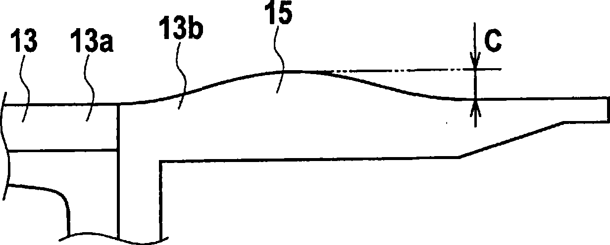
[0052] In the moving walk that is the passenger conveyor device according to the third embodiment, the guide rail 31 arranged along the circular movement direction of the conveyor chain 7 is provided in the truss 1 . The guide rail 31 is composed of a single central guide rail 31a and two end guide rails 31b. Furthermore, the end part guide rail 31b is fixed to the both ends of the center part guide rail 31a with a bolt. On the end guide rails 31b which are a part of the guide rails 31, two bent portions 15 formed protruding in a shape toward the outer peripheral side of the circular movement path of the conveyor chain 7 are provided each. In the guide rail 31 , in the front and rear regions sandwiching the curved portion 15 , the heights from the respective regions to the top of the curved portion 15 are set to be different. For example, the height "I" to the top of the curved portio...


PUM


Abstract

A passenger conveyor device having a conveyor chain (7) connecting link plates (8) by using connection shafts (9) and circulating between two sprockets, a guide rail laid along the circulation direction of the conveyor chain (7) and having a curve section projecting in a mountain-like shape, guide rollers (10) attached to the link plates (8) and moving engaged with the guide rail, and a pressing rail placed on the outer peripheral side of that portion of the guide rail that is in a region facing the curve section. A fixed section (12a) provided at a tread section (12) is fixed to an edge section (8a) on the outer peripheral side of a link plate (8), and the height from the edge section (8a) to the surface (12b) of the outer peripheral side of the fixed section (12a) is set to a level that does not cause the fixed section (12) to come into contact with the pressing rail.

Description

technical field [0001] The present invention relates to passenger conveyor devices such as moving walks or escalators. Background technique [0002] A passenger conveyor device such as a moving walkway or an escalator includes a plurality of treads on which passengers ride, and a pair of endless conveyor chains connecting the treads. The conveyor chain is spanned between a pair of sprockets provided on the inlet side and the outlet side. In addition, by rotating the sprocket with a driving device such as a motor, the stepping portion circulates between the entrance and the exit together with the conveyor chain. [0003] The connection between the stepping part and the conveyor chain is performed by fixing the fixing parts provided at both ends of the stepping part to the outer peripheral side edge parts of the chain plates of the conveyor chain. [0004] In addition, the conveyor chain is formed by connecting a plurality of link plates with a plurality of connecting shafts...

Claims


Application Information

Patent Timeline
Patent Type & Authority Applications(China)
IPC IPC(8): B66B23/14B66B23/02
CPCB66B23/026B66B23/022
Inventor 菊池孝幸高泽理志村上伸
Owner TOSHIBA ELEVATOR KK
Why Eureka
Try Eureka