Pneumatic vehicle tyre

A technology for pneumatic tires and vehicles, applied to the reinforcement layer of pneumatic tires, heavy tires, heavy vehicles, etc., can solve the problems of high weight and cost, achieve high lateral stiffness and bending stiffness, good wear characteristics, and improve durability Effect

Inactive Publication Date: 2013-01-02
CONTINENTAL REIFEN DEUTSCHLAND GMBH
View PDF6 Cites 8 Cited by
  • Summary
  • Abstract
  • Description
  • Claims
  • Application Information

AI Technical Summary

Problems solved by technology

However, such a 0° belt ply requires a higher amount of steel cord material, and the associated higher weight and cost, relative to a sloped belt ply

Method used


Image

  • Pneumatic vehicle tyre
  • Pneumatic vehicle tyre
  • Pneumatic vehicle tyre

Examples


Embodiment Construction

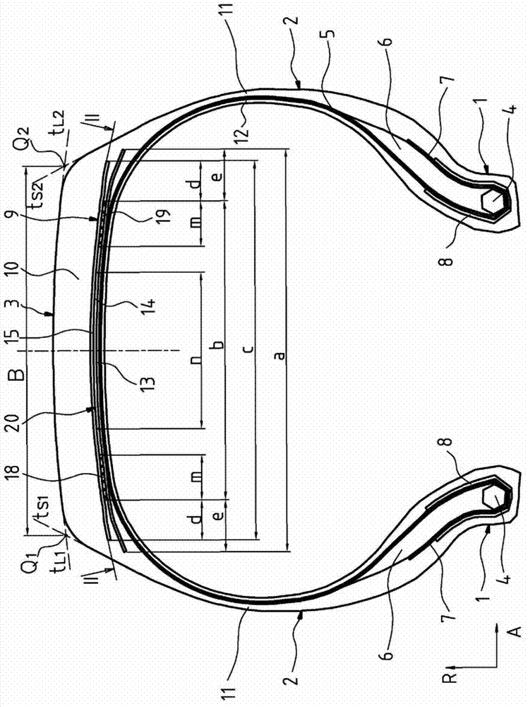
[0069] figure 1 and figure 2 Shown is a commercial vehicle pneumatic tire of the radial configuration type having two sidewalls 2 extending in the radial direction R of the vehicle tire, and a tire formed axially between them. Crown area 3. These side walls 2 are designed at the end of their extension directed inwards in the radial direction R with a bead area 1 in which a bead core 4 of a known type is formed, which in the It is stretch-resistant in the circumferential direction U and extends in the circumferential direction U over the circumference of the tire. The bead cores 4 are designed to be wound in a known manner from a wire extending in the circumferential direction U of the pneumatic vehicle tire and embedded in rubber. An apex (core filler) 6 of triangular cross-section, made of a hard rubber material, is formed on the bead cores 4 in a conventional manner. The vehicle pneumatic tire is designed to have a carcass 5 extending outward in the radial direction R ...


PUM


Abstract

A pneumatic vehicle tyre for commercial vehicles, comprising a carcass (5), a breaker belt (9) and a profiled tread rubber (10), wherein the breaker belt (9) is formed by at least three belt plies (13, 14, 15), of which the radially inner ply (13) and the radially outer ply (15) are formed as working plies with parallel steel reinforcing elements (23, 25) embedded in rubber, wherein the reinforcing elements (23, 25) of the working plies (13, 15) have opposed axial directions of inclination and an angle in relation to the circumferential direction of 10 DEG -45 DEG , and wherein the belt ply (14) arranged between the two working plies (13, 15) is divided in the axial direction and is formed by two axial outer peripheral ply portions (18, 19) and one central ply portion (14) arranged axially between said peripheral portions, wherein the two peripheral ply portions (18, 19); are formed as zero degree plies with reinforcing elements (28, 29), which include an angle in relation to the circumferential direction U of 0 DEG -5 DEG , and the central ply portion (14) is formed with reinforcing elements (24) which include an angle in relation to the circumferential direction U of 5 DEG -90 DEG.

Description

technical field [0001] The present invention relates to a vehicle pneumatic tire for commercial vehicles having a carcass, with a belt established radially outside the carcass, and with a A shaped tread built on the belt formed of at least three belt plies arranged from radially inner to radially outer, in particular one above the other stacked, the radially inner belt ply and the radially outer belt ply constitute working plies with parallel steel reinforcements embedded in rubber, where The reinforcements of the radially inner belt ply form an angle α with respect to the circumferential direction U in their orientation, 10° ≤ α ≤ 45°, and the reinforcements of the radially outer belt ply In their orientation form an angle γ with respect to the circumferential direction U, 10° ≤ γ ≤ 45°, and wherein the reinforcements of the radially inner working ply, when viewed in the circumferential direction U of the vehicle tire, have Opposite direction of axial inclination to the rei...

Claims


Application Information

Patent Timeline
Patent Type & Authority Applications(China)
IPC IPC(8): B60C9/20B60C9/22
CPCB60C2009/2041B60C9/2006B60C2009/2038B60C2009/2219B60C2200/06B60C2009/2016B60C2009/2019B60C2009/2022B60C2009/2223
Inventor 特蕾西娅·贝克尔迪特尔·赫罗米马丁·约瑟夫·克劳斯海因茨·马楚尔
Owner CONTINENTAL REIFEN DEUTSCHLAND GMBH
Why Eureka
Try Eureka