
Z-steel stacking equipment

A stacking material and equipment technology, applied in the field of Z-shaped steel stacking equipment, can solve the problems of poor stacking, poor stacking effect, and rising labor costs, and achieve convenient clamping, good stacking effect, and production high efficiency effect

Active Publication Date: 2013-01-09
XIAMEN ZHENGLIMING METALLURGICAL MACHINERY
View PDF8 Cites 10 Cited by
  • Summary
  • Abstract
  • Description
  • Claims
  • Application Information

AI Technical Summary

Problems solved by technology

At present, quite a few domestic manufacturers still use manual lifting of the cut profiles off the supporting table for stacking, which has the following disadvantages: 1. It is a waste of manpower and inefficient; 2. With the reduction of labor force population and Fewer and fewer people are willing to do such simple and repetitive heavy physical work, and labor costs continue to rise
Due to the special shape of the Z-shaped steel itself, its cross-section is centrally symmetrical, so whether it is pushed horizontally or dropped directly vertically, it will not be able to stack well, and the stacking effect is not good. Usually, it needs to be manually corrected after pushing the stack. stacking effect

Method used


Image

  • Z-steel stacking equipment
  • Z-steel stacking equipment

Examples


Embodiment Construction

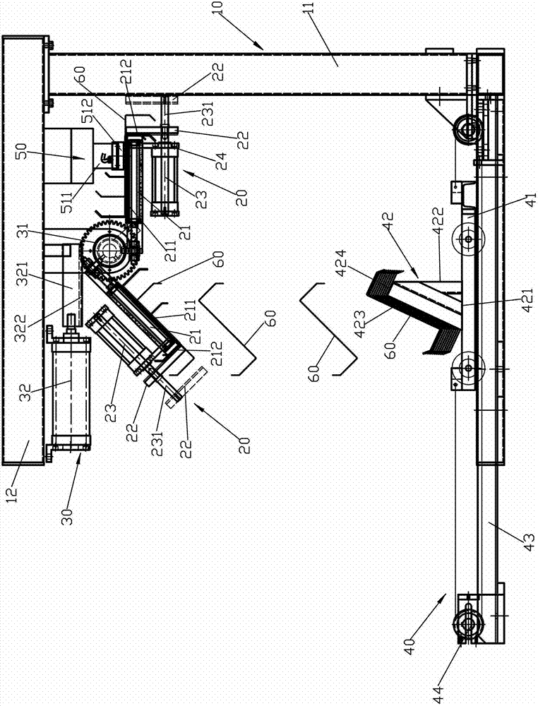
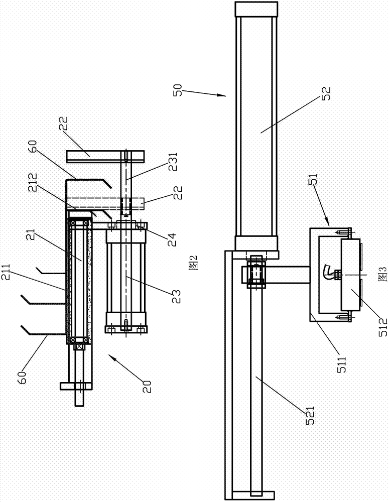
[0033] Z-shaped steel stacking equipment, please refer to figure 1 , including a frame 10, a clamping device 20, a rotating device 30, a stacking platform device 40 and a pulling device 50. This equipment is mainly used in the steel structure industry. It is an automatic process for separating Z-shaped steel from the forming machine to the packaging stage. It is used to stack the Z-shaped steel 60 formed on the forming machine on the stacking table. The Z-shaped steel 60, such as figure 1 and figure 2 As shown, at least one middle side and two small sides are included, and some small sides are provided with inverted edges as required.

[0034] The frame 10 includes a vertical column 11 and a beam 12 fixed on the top of the vertical column 11 .

[0035] For the clamping device 20, please refer to the figure 1 and figure 2 , including a workbench 21, a clamping seat 22 that can move relative to the workbench 21, and a clamping power device 23 installed on the workbench 21...


PUM


Abstract

The invention discloses Z-steel stacking equipment, comprising a machine frame 10, a clamping device 20, a rotary device 30 and a stacking platform device 40. The clamping device 20 comprises a workbench 21, a clamping base 22 and a clamping power device 23, wherein the clamping power device 23 is connected with the clamping base 22 in a transmission manner to drive the clamping base 22 to move between a releasing position and a clamping position in a manner relative to the workbench 21. The rotary device 30 comprises a rotary base 31 and a rotary power device 32, the workbench 21 is fixedly connected with the rotary base 31, the rotary power device 32 is connected with the rotary base 31 in a transmission manner to drive the rotary base 31 and the workbench 21 to rotate between a feeding position and a discharge position in a manner relative to the machine frame 10. The stacking platform device 40 comprises a stacking platform 41, and the clamping device 20 arranged at the discharge position is positioned above the stacking platform 41. The Z-steel stacking equipment has the following advantages: automatic stacking is realized, and the production efficiency is high; the production flow is simplified, and the packaging in the next stage is facilitated; the stacking effect is good, and the artificial finishing is not needed; and the equipment structure is simple, and the cost is low.

Description

technical field [0001] The invention relates to a Z-shaped steel stacking equipment. Background technique [0002] Z-shaped steel plays the main load-bearing role in steel structure construction, and it has the characteristics of large weight per unit length and long length. At present, quite a few domestic manufacturers still use manual lifting of the cut profiles off the supporting table for stacking, which has the following disadvantages: 1. It is a waste of manpower and inefficient; 2. With the reduction of labor force population and Fewer and fewer people are willing to do such simple and repetitive labor-intensive work, and labor costs continue to rise. [0003] In response to the above shortcomings, some people have proposed solutions, such as stackers on the existing market, and their principles have the following categories: [0004] 1. Electromagnet sucker handling. Because the length of Z-shaped steel finished product is long, has 12 meters, even has 16 meters,...

Claims


Application Information

Patent Timeline
Patent Type & Authority Applications(China)
IPC IPC(8): B65G57/08B65G57/20
Inventor 黄溢忠冉隆军何昌甫程国宝朱卿秀
Owner XIAMEN ZHENGLIMING METALLURGICAL MACHINERY
Learn More