
Light guide plate and electronic device provided with same

A technology for electronic devices and light guide plates, which is applied to lighting devices, lighting device parts, optics, etc., can solve the problems of inability to uniformly guide light from light sources, uneven brightness, and affect the light guide effect, and improve the light guide effect. , the effect of reducing the brightness difference

Inactive Publication Date: 2013-01-09
HONG FU JIN PRECISION IND (SHENZHEN) CO LTD +1
View PDF2 Cites 2 Cited by
  • Summary
  • Abstract
  • Description
  • Claims
  • Application Information

AI Technical Summary

Problems solved by technology

However, most of the current light guide plates are often unable to uniformly transmit the light emitted by the light source. Usually, the closer to the light source on the light guide plate, the more light is exported, while the farther away from the light source, the less light is exported. Uneven brightness affects the light guiding effect

Method used


Image

  • Light guide plate and electronic device provided with same
  • Light guide plate and electronic device provided with same
  • Light guide plate and electronic device provided with same

Examples


Embodiment Construction

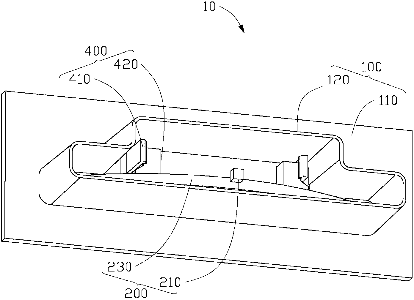
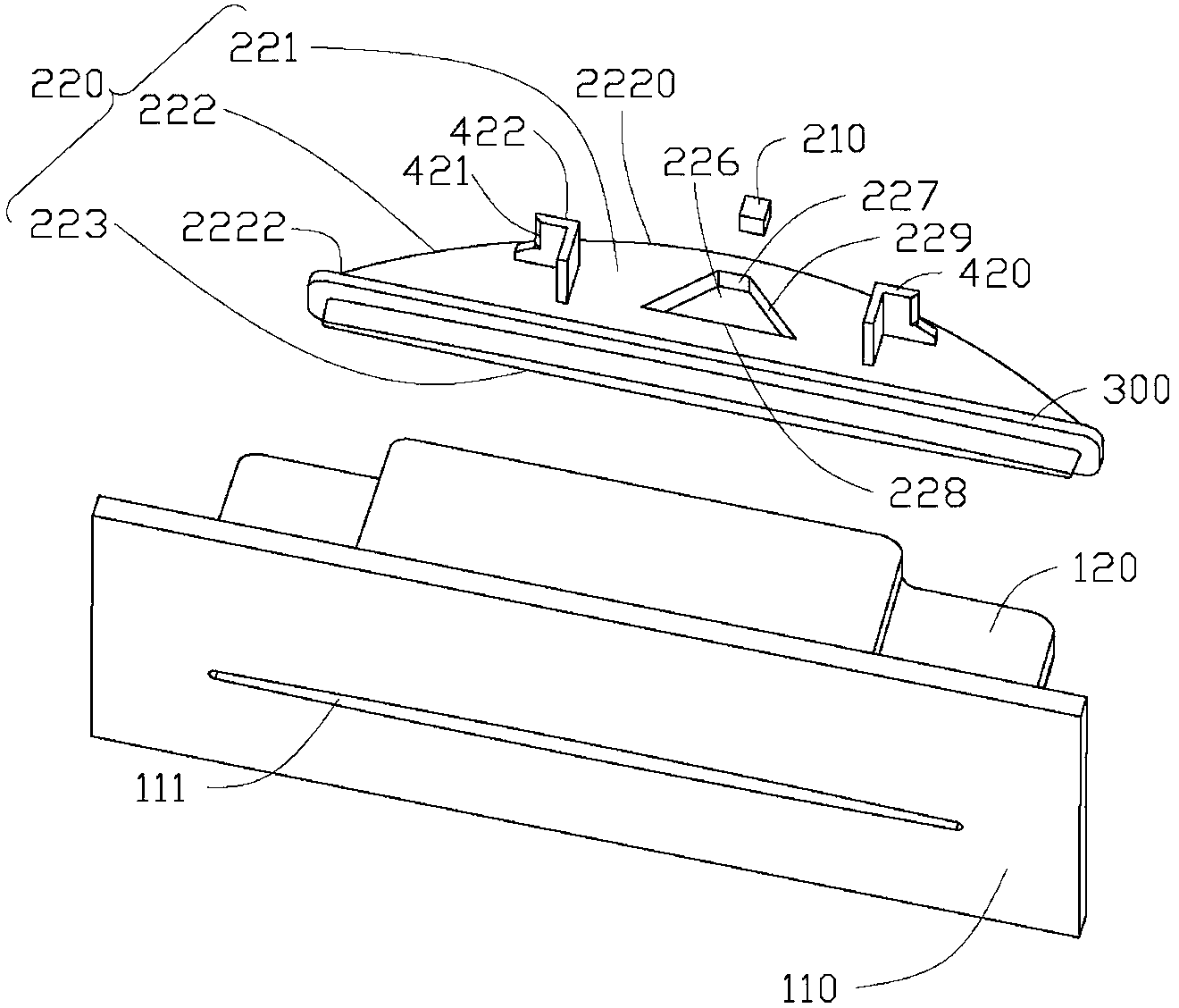
[0013] Please refer to figure 1 , in this embodiment, the electronic device 10 has a housing 100, a light-emitting component 200 disposed on the housing 100, a blocking member 300 disposed on the light-emitting component 200 (such as figure 2 shown) and the engaging structure 400 for engaging the light-emitting component 200 to the casing 100 . The light emitted by the light-emitting component 200 can illuminate a part of the housing 100 so as to achieve the functions of identification, warning or aesthetics of the electronic device 10 .

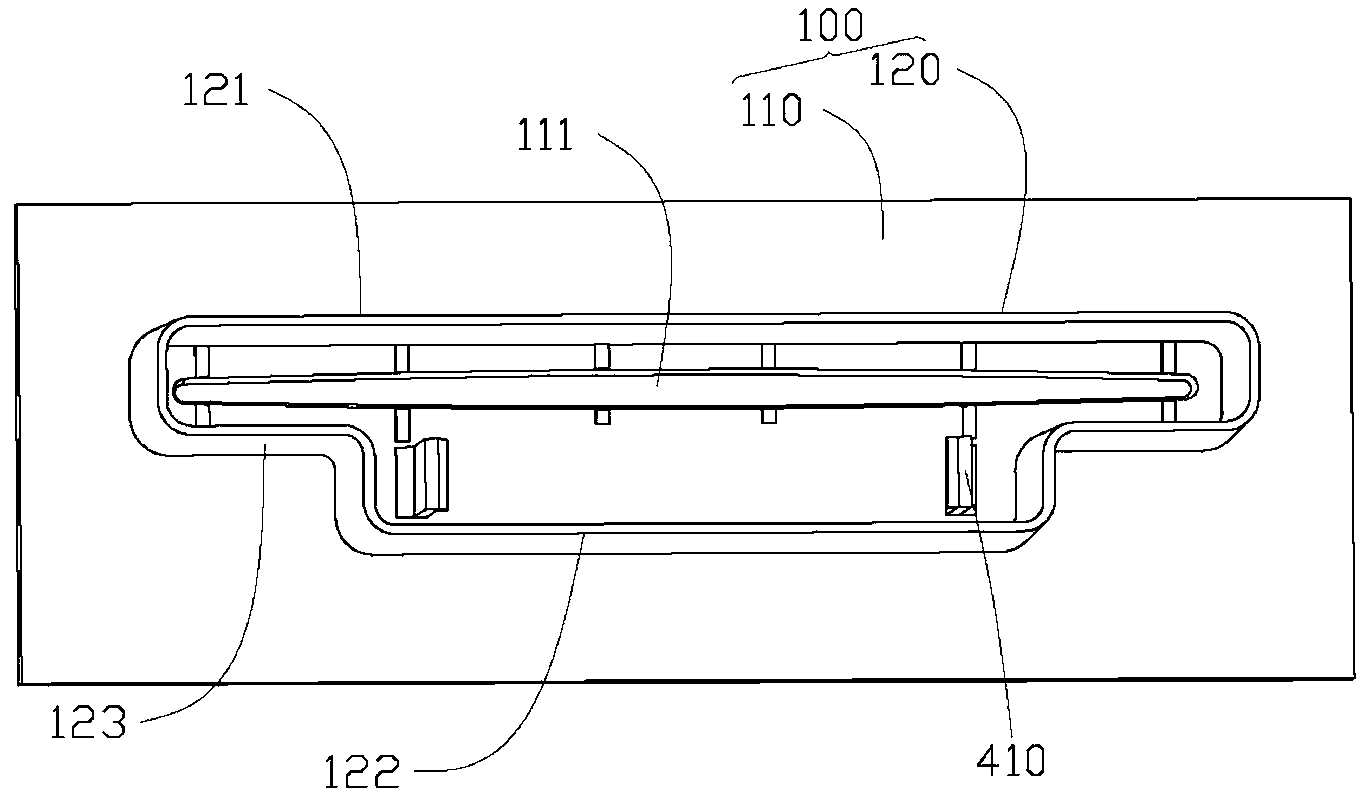
[0014] The casing 100 includes a panel 110 , and a receiving portion 120 horizontally extending inward from the panel 110 and used for receiving the light emitting assembly 200 . The panel 110 is provided with an elongated through hole 111 for accommodating the light-emitting surface of the light guide plate 220 of the light-emitting component 200 therein. Such as image 3 and Figure 4 As shown, the receiving portion 120 is arranged ar...


PUM


Abstract

Provided is a light guide plate, comprising two opposite plate surfaces and two opposite side edges connecting the two opposite plate surfaces, wherein one side edge includes a light-in surface, the other side edge includes a light-out surface, and the distance between the light-in surface and the light-out surface decreases with the increase of the distance between the light-in surface and a light source. The invention further provides an electronic device provided with the light guide plate. The distance between the light-in surface and the light-out surface of the light guide plate of the invention decreases with the increase of the distance between the light-in surface and the light source, which is helpful for reducing the brightness difference between two ends of the light-out surface and improving the light guiding effect of the light guide plate.

Description

technical field [0001] The invention relates to an electronic device, in particular to an electronic device with a light-emitting component. Background technique [0002] Most of the existing electronic devices have a light-emitting component for at least partially illuminating the electronic device so that the electronic device has a marking function or a decorative function. The light-emitting component generally includes a light guide plate, which is used to evenly guide the light emitted by the light source to the part of the electronic device that needs to be illuminated. Therefore, the light guide plate is a key part of the light-emitting component, which must be able to guide the light emitted by the light source evenly, so that the light-emitting component has a good lighting effect. However, most of the current light guide plates are often unable to uniformly transmit the light emitted by the light source. Usually, the closer to the light source on the light guide ...

Claims


Application Information

Patent Timeline
Patent Type & Authority Applications(China)
IPC IPC(8): G02B6/00F21V8/00F21S2/00F21V17/00
CPCG02B6/00G02B6/0045F21S2/00G06F1/165G06F1/1656F21V17/00G06F1/00
Inventor 王远明万雪峰李兆勇
Owner HONG FU JIN PRECISION IND (SHENZHEN) CO LTD
Learn More