
Display device

A display device and display technology, applied in the directions of optics, instruments, electrical components, etc., can solve problems such as image contrast reduction, and achieve the effect of suppressing the decline in contrast ratio.

Inactive Publication Date: 2013-01-09
SONY CORP
View PDF3 Cites 2 Cited by
  • Summary
  • Abstract
  • Description
  • Claims
  • Application Information

AI Technical Summary

Problems solved by technology

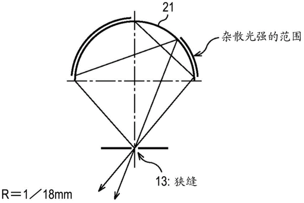
In this case, the contrast of the image is reduced because the brightness near the reflected position appears brighter than the original brightness

Method used


Image

  • Display device
  • Display device
  • Display device

Examples


Embodiment Construction

[0021] Hereinafter, preferred embodiments of the present disclosure will be described in detail with reference to the accompanying drawings. It should be noted that, in this specification and the appended drawings, structural elements that have substantially the same function and structure are denoted with the same reference numerals, and repeated explanation of these structural elements is omitted.

[0022] Hereinafter, preferred embodiments of the present disclosure will be described in detail with reference to the accompanying drawings.

[0023]

[0024] [Configuration Example of Omnidirectional Stereoscopic Image Display Device]

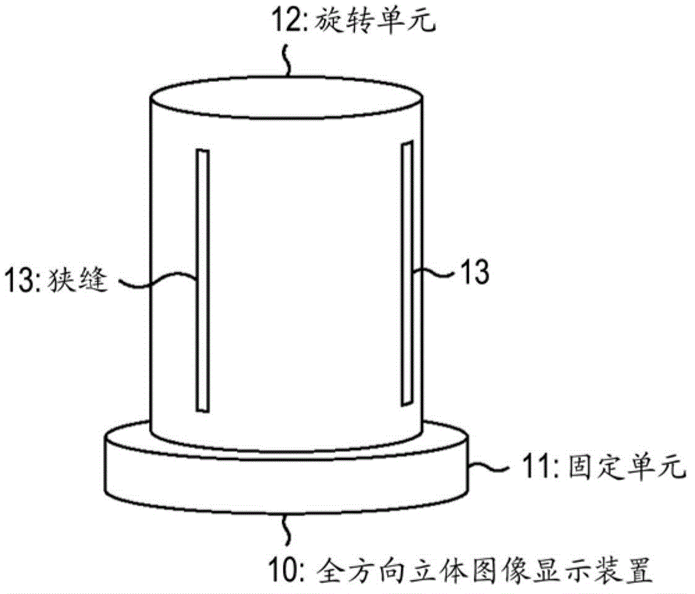
[0025] figure 1 is an external view showing an omnidirectional stereoscopic image display device according to an embodiment of the present disclosure. This omnidirectional stereoscopic image display device 10 includes a fixing unit 11 as a base and a rotating unit 12 having a cylindrical shape and rotating at high speed.

[0026] In this omn...


PUM


Abstract

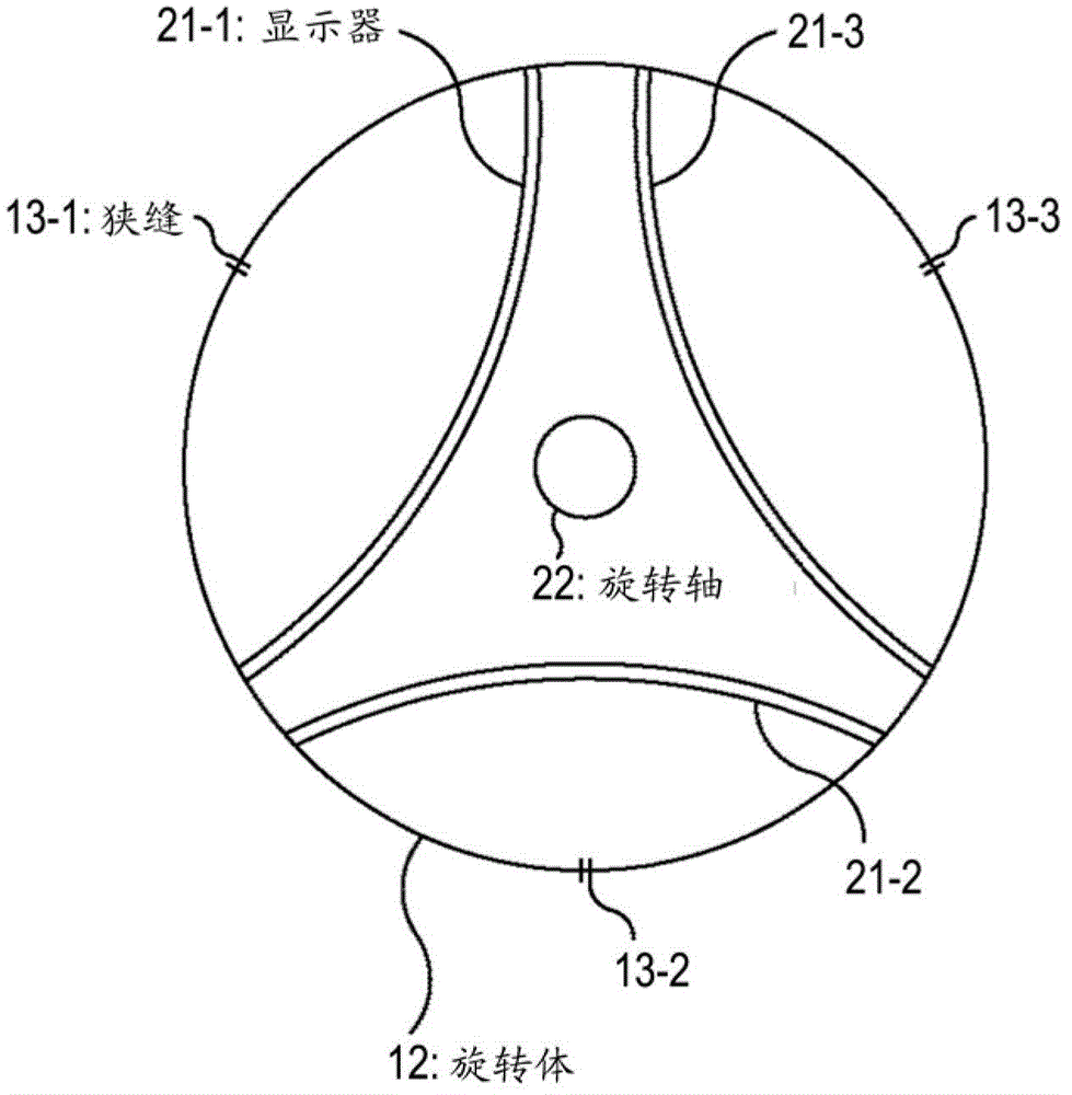
Provided is a display device including a housing whose side surface has one or more slits, and a display that is mounted in the housing and has a substantially arc shape, wherein an image displayed on the display is visually recognized beyond the slit when the housing rotates, and a curvature of the display having the substantially arc shape is formed so that stray light resulting from a specular reflection does not occur.

Description

technical field [0001] The present disclosure relates to a display device, for example, to a display device in which the display is configured as a curved display made of a large number of light emitting diodes (LEDs). Background technique [0002] In a related field, there is a three-dimensional display technology in which stereoscopic images are displayed on flat displays used in television receivers and the like. For example, among the three-dimensional display technologies, there is a technology in which the parallax of the left and right eyes of a human when viewing a display is utilized. Specifically, for example, by alternately displaying an image for the left eye and an image for the right eye on a flat display and using a polarizing filter or the like, stereoscopic vision can be realized so that only the image for the left eye is displayed by the left eye Viewed, and images intended for the right eye only are viewed by the right eye. [0003] In contrast, various ...

Claims


Application Information

Patent Timeline
IPC IPC(8): G02B27/22H04N13/04G03B35/18
CPCH04N13/04G02B27/22G03B35/18G02B27/2214G03B35/24G02B27/2285H04N13/0409H04N13/31G02B30/54G02B30/27
Inventor 小林出志柳泽裕幸菊池启记
Owner SONY CORP
Learn More