Hydraulic distributer

A technology for hydraulic distributors and housings, which is applied in the direction of fluid pressure actuation devices, fluid pressure actuation system components, servo motor components, etc., which can solve problems such as poor reliability, poor oil circuit sealing performance, and few functions, and achieve reliable The effect of high performance, meeting requirements, and compact structure

Active Publication Date: 2015-04-29
SHANDONG WEIFANG LUZHONG TRACTOR
View PDF10 Cites 0 Cited by
  • Summary
  • Abstract
  • Description
  • Claims
  • Application Information

AI Technical Summary

Problems solved by technology

However, due to the simple structure of the oil circuit and the poor sealing performance between the oil circuits, the traditional hydraulic distributor has the defects of few functions and poor reliability, which affects its popularization and use.

Method used


Image

  • Hydraulic distributer
  • Hydraulic distributer
  • Hydraulic distributer

Examples


Embodiment Construction

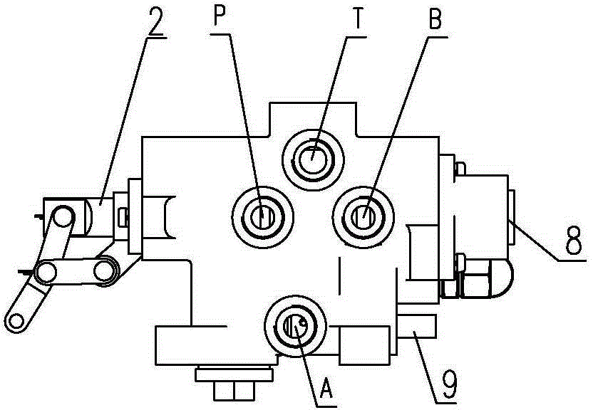
[0015] Such as figure 1 As shown, a hydraulic distributor according to the present invention includes a housing 1 and a valve stem 2, an oil passage is arranged in the inner cavity of the housing 1, the valve stem 2 is inserted in the housing 1, and the outer surface of the housing 1 The surface is provided with an oil inlet P, an oil return port T, a positive direction control port A, and a reverse direction control port B. The outer surface of the valve stem 2 located in the inner cavity of the housing 1 is provided with an annular oil groove. The front end of the valve stem 2 A rocker arm 21 is hinged.

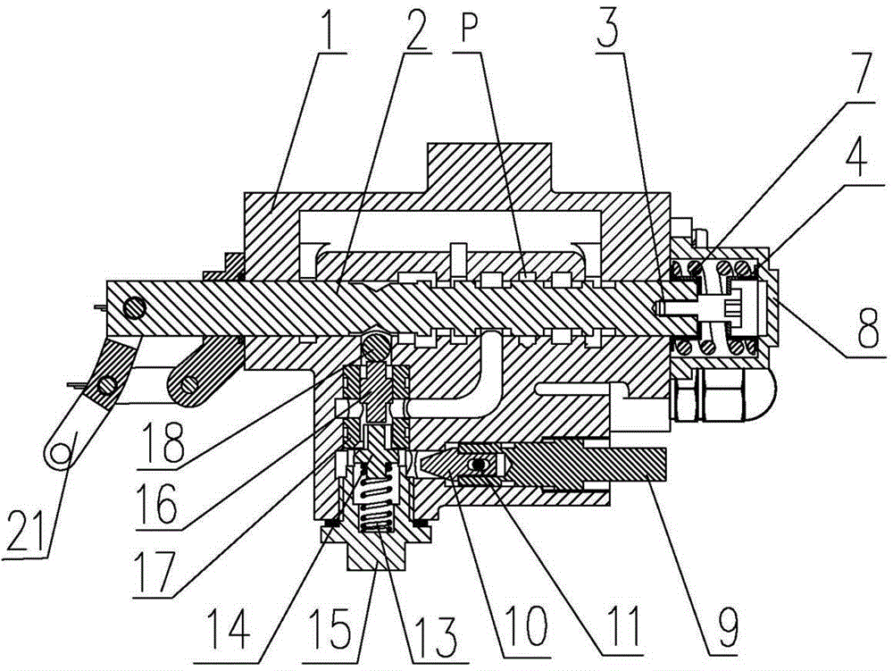
[0016] Such as figure 2 As shown, an automatic return device is installed at the rear end of the valve stem 2, and the automatic return device includes a return seat 4, a return screw 3, and a return spring arranged between the return seat 4 and the valve stem 2 7. The end surface of the return seat 4 is provided with a groove for accommodating the return screw 3, and th...


PUM


Abstract

The invention relates to a hydraulic distributer which comprises a shell and a valve rod, an oil channel is arranged in an inner cavity of the shell, the valve rod is inserted into the shell, an oil inlet, an oil return port, a positive direction control port and a negative direction control port are arranged on the outer surface of the shell, an automatic return device is mounted at the rear end of the valve rod and comprises a return seat, a return screw and a return spring arranged between the return seat and the valve rod, a groove for accommodating the return screw is arranged on the end face of the return seat, a screw hole penetrating through the return seat is arranged at the center of the groove, and the return screw penetrates through the screw hole on the return seat to be screwed on the end face of the valve rod. The hydraulic distributer is compact in structure and high in reliability, integrates ascending, descending, middle standing and floating functions, has a hydraulic outward output function, can provide power for other hydraulic equipment and is adjustable in descending speed.

Description

technical field [0001] The invention relates to a hydraulic distributor. Background technique [0002] Construction machinery such as tractors generally use hydraulic distributors to transmit torque, which has the characteristics of no noise and high transmission efficiency. In the process of engineering work, in addition to the lifting and lowering functions, the hydraulic distributor is also required to be able to achieve neutral and floating functions. The so-called neutral is to stop the mechanical arm at a certain intermediate position and lock it, and will not change its position due to external force; the so-called Floating means that the hydraulic device stops working, and the mechanical arm can change its position with the action of external force. However, due to the simple structure of the oil circuit and the poor sealing performance between the oil circuits, the traditional hydraulic distributor has the defects of few functions and poor reliability, which affect...

Claims


Application Information

Patent Timeline
Patent Type & Authority Patents(China)
IPC IPC(8): F15B13/02F15B21/00
Inventor 胥丽颖胥正东胥宏伟
Owner SHANDONG WEIFANG LUZHONG TRACTOR
Why Eureka
Try Eureka