Flange manhole for self-balancing horizontal rotary cover

A technology of covering flanges and horizontal rotation, which is applied to pressure vessels, fixed-capacity gas storage tanks, mechanical equipment, etc., and can solve problems such as potential safety hazards, sparks, and easily damaged flange joint sealing systems, and achieve safe opening. Effect

Inactive Publication Date: 2013-01-16
TAIJUNE BOILER IND KUSN
7 Cites 2 Cited by

AI-Extracted Technical Summary

Problems solved by technology

But the disadvantage is that the flange cover is often heavy for manholes with large diameter and high nominal pressure.
For example: the weight of flange BL500-16RF (HG/T20592) is 133Kg, the weight of flange BL600-16RF (HG/T20592) reaches 226Kg, and manual opening is even more laborious
For the manhole of the horizontal hanging cover, since the rotating arm is opened by rotating the center of the casing, friction will be generated between the flange cover, the gasket and the flange, which is easy to damage the sealing system of the flange joint
And if it is a carbon steel manhole, the flange cover and the flange will produce sparks ...

Method used

Embodiment: a kind of self-balancing horizontal revolving cover flange manhole, described revolving cover flange manhole is composed of manhole 1, flange 2 fixed on the manhole upper end and the revolving cover that is used to seal the manhole 3, the rear ends of the flange 2 and the rotary cover 3 are rotatably connected by a connecting shaft 4, and a spring cylinder balance system is provided, and the spring cylinder balance system is composed of a spring cylinder 5, a connecting piece and a spring cylinder The lug 6 is formed, the connecting piece is connected with the connecting shaft 4, the lower end of the spring cylinder lug 6 is fixed on the upper surface of the revolving cover 3, and the spring cylinder 5 is mainly composed of a cylinder body 51, a spring 52 and a pull rod. 53, the rear end of the pull rod 53 is connected to the connector, the spring 52 is set on the pull rod 53, the cylinder 51 is set outside the spring 52, the cylinder 51 and the spring The upper end of the cylinder lug 6 is connected, the rear end of the spring 52 is pressed against the inner surface of the rear end of the ...

Abstract

The present invention discloses a flange manhole for a self-balancing horizontal rotary cover. The flange manhole for the rotary cover consists of a manhole, a flange fixed at the upper end of the manhole and a rotary cover used for sealing the manhole, wherein the rear ends of the flange and the rotary cover are rotatably connected through a connecting shaft. The flange manhole is also provided with a spring cylinder balancing system consisting of a spring cylinder, a connecting piece and a spring cylinder support lug. The flange manhole for the self-balancing horizontal rotary cover is provided with the spring cylinder balancing system, and the torque formed by the tension of the spring cylinder is equal to that formed by the gravity of the rotary cover, so that the rotary cover can be balanced at any point within the range of 0-90 degrees, the opening of the rotary cover is safe, and the labor is saved.

Application Domain

Pressure vessels

Technology Topic

Flange

Image

  • Flange manhole for self-balancing horizontal rotary cover
  • Flange manhole for self-balancing horizontal rotary cover
  • Flange manhole for self-balancing horizontal rotary cover

Examples

  • Experimental program(1)

Example Embodiment

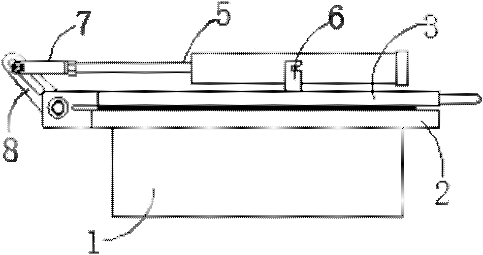
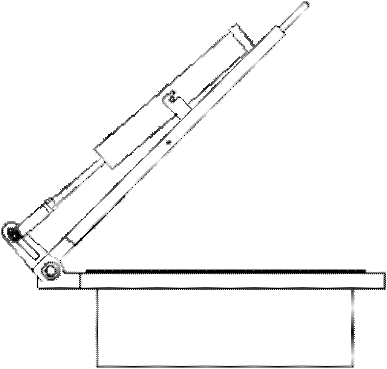
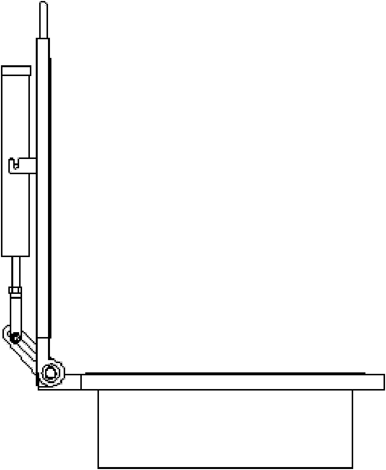
[0020] Embodiment: a self-balancing horizontal revolving cover flange manhole, the revolving cover flange manhole is composed of a manhole 1, a flange 2 fixed to the upper end of the manhole, and a revolving cover 3 for sealing the manhole, The rear ends of the flange 2 and the revolving cover 3 are rotatably connected by a connecting shaft 4, and a spring cylinder balance system is provided. The spring cylinder balance system consists of a spring cylinder 5, a connecting piece and a spring cylinder lug 6 The connecting member is connected with the connecting shaft 4, the lower end of the spring cylinder lug 6 is fixed on the upper surface of the revolving cover 3, and the spring cylinder 5 is mainly composed of a cylinder body 51, a spring 52 and a tie rod 53, The rear end of the pull rod 53 is connected to the connecting piece, the spring 52 is sleeved on the pull rod 53, the cylinder 51 is sleeved outside the spring 52, and the cylinder 51 is connected to the spring cylinder lug 6 is connected at the upper end, the rear end of the spring 52 presses against the inner surface of the rear end of the cylinder 51 and the front end of the spring 52 is positioned and connected with the front end of the pull rod 53, and the spring 52 is in a compressed state. The front and back mentioned in the present invention correspond to the right and left of the drawings, respectively. The self-balancing horizontal slewing cover flange manhole of the present invention uses the spring cylinder pull force to form a moment equal to the torque formed by the gravity of the slewing cover, so as to achieve the purpose of safety and labor saving when the slewing cover is opened. This structure can make the slewing cover at 0 A balance can be reached at any point within the range of ~90°. In specific implementation, the spring cylinder can be made standardized, and the magnitude of the torque can be achieved by changing the height of the spring cylinder lug.
[0021] A connecting head 7 and a spring cylinder fixing plate 8 are provided. The connecting head 7 and the spring cylinder fixing plate 8 are rotatably connected to form the connecting piece. The connecting head 7 is fixedly connected to the rear end of the pull rod 53, so The spring fixing plate 8 is fixedly connected to the connecting shaft 4.
[0022] A polytetrafluoroethylene bush 54 is provided on the contact surface of the cylinder 51 and the tie rod 53. The polytetrafluoroethylene bushing is used to prevent friction between the tie rod and the cylinder.
[0023] A cylinder cover 55 is fixed at the front end of the cylinder 51.
[0024] At least one spring 52 is provided, and a plurality of ring-shaped spring seats 56 are sleeved on the pull rod 53. The adjacent springs 52 are separated by the spring seats 56. Among all the springs 52, the rearmost spring The rear end abuts against the inner surface of the rear end of the cylinder body 51.
[0025] A nut 57 is fixed at the front end of the pull rod 53, a spring seat 56 is provided behind the nut 57 close to the nut, and the front end of the spring at the front end of all the springs 52 abuts against the spring seat 56 abutting the nut.

PUM

no PUM

Description & Claims & Application Information

We can also present the details of the Description, Claims and Application information to help users get a comprehensive understanding of the technical details of the patent, such as background art, summary of invention, brief description of drawings, description of embodiments, and other original content. On the other hand, users can also determine the specific scope of protection of the technology through the list of claims; as well as understand the changes in the life cycle of the technology with the presentation of the patent timeline. Login to view more.
Why Eureka
Try Eureka