Safe position-limiting mechanism for automatic rotary table conveying device

A technology of limit mechanism and conveying device, which is applied in the direction of conveyor control device, conveyor, conveyor objects, etc.

Active Publication Date: 2018-11-06
HENAN UNIV OF SCI & TECH
View PDF5 Cites 5 Cited by
  • Summary
  • Abstract
  • Description
  • Claims
  • Application Information

AI Technical Summary

Problems solved by technology

[0008] The object of the present invention is to provide a safety limit mechanism for the automatic turntable conveying device in order to solve the problems of the above-mentioned existing automatic turntable conveying device, by installing a safety limit on the existing automatic turntable conveying device mechanism to eliminate the safety hazards in the above-mentioned existing turntable conveying device and meet the requirements of the automatic conveying line for the automatic turntable conveying device

Method used


Image

  • Safe position-limiting mechanism for automatic rotary table conveying device
  • Safe position-limiting mechanism for automatic rotary table conveying device
  • Safe position-limiting mechanism for automatic rotary table conveying device

Examples


specific Embodiment approach

[0030] Referring to the accompanying drawings, the specific implementation is as follows:

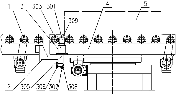
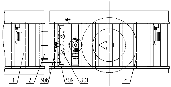
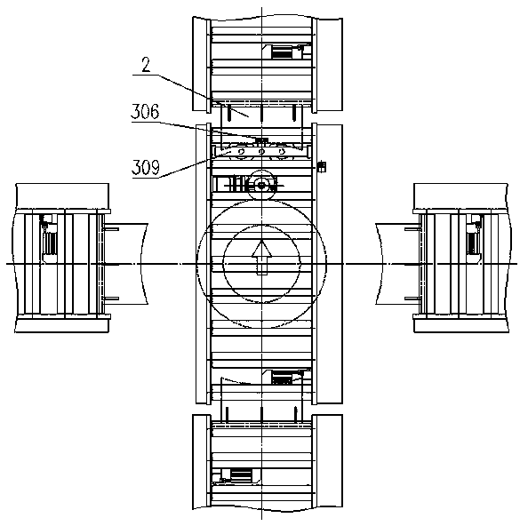
[0031] A safety limit mechanism for an automatic turntable conveying device, including a stopper 3 installed at the output end of the turntable roller table 4 and a pressure plate 2 installed at the end of the conveying roller table 1 facing the turntable roller table 4, the stopper 3 includes Two sleeves 303 installed on the end surface of the bottom plate of the turntable roller table 4, a vertical support rod 302 is inserted on the two sleeves 303, and one end of the two support rods 302 located in the sleeve 303 passes through A respective spring 304 is connected to the bottom plate of the turntable roller table 4, and the ends of the two support rods 302 away from the sleeve 303 are connected to the bottom of the same cuboid block 301,

[0032] The stopper block 301 is located between two adjacent rollers of the turntable roller table 4, and the length of the stopper block 301 alon...


PUM


Abstract

The invention relates to a safe position-limiting mechanism for an automatic rotary table conveying device. The safe position-limiting mechanism for the automatic rotary table conveying device comprises a stopper arranged on a rotary table roller way, and a pressing plate arranged on a conveying roller way, wherein the stopper comprises two sleeves arranged on a bottom plate of the rotary table roller way; support rods are inserted into the two sleeves; one ends of the two support rods are connected with the bottom plate of the rotary table roller way through springs; the other ends of the twosupport rods are connected with the bottom part of one long strip-shaped stopper block; the top part of the stopper block is located above the rotary table roller way so as to stop a workpiece; the bottom part of the stopper block is connected with one end of a connecting rod; a rolling wheel seat and a rolling wheel are arranged at the other end, penetrating through the bottom plate of the rotary table roller way, of the connecting rod; two sections of inclined surfaces with opposite inclined directions are arranged at the bottom end of the pressing plate; the pressing plate is located on arotation path of the rolling wheel rotating along with the rotary table roller way, so that the rolling wheel contacts one section of the two sections of inclined surfaces and rolls along the inclinedsurface so as to drive the stopper block to move downwards, and the top part of the stopper block is located under the rotary table roller way; and through the elastic acting forces of the springs, the stopper block is reset after the rolling wheel and the pressing plate are separated.

Description

technical field [0001] The invention relates to the field of automatic turntable conveying equipment, in particular to a safety limit mechanism for an automatic turntable conveying device. Background technique [0002] With the improvement of the level of automated production in modern industry, in order to improve production efficiency and reduce labor intensity, automated conveyor lines have been widely used. The roller conveyor system is connected to realize the automatic production and transportation of workpieces; [0003] In the automatic conveying line, when the workpiece needs to change the conveying direction, it is necessary to install a turntable conveying device between the two sections of rollers in the conveying line. The workpiece is first sent to the turntable roller installed on the turntable conveying device, and then on the turntable roller Stay and turn with the roller table of the turntable, and then send it from the roller table of the turntable to the...

Claims


Application Information

Patent Timeline
Patent Type & Authority Applications(China)
IPC IPC(8): B65G43/08B65G13/00B65G47/64B65G41/00B65G47/88
CPCB65G13/00B65G41/002B65G43/08B65G47/648B65G47/8815B65G2203/042
Inventor 张志红谢金法解晓琳岳菊梅马浩霖
Owner HENAN UNIV OF SCI & TECH
Why Eureka
Try Eureka