Accumulator having multiple accumulator cells

A technology for accumulators and electronic components, applied in the direction of electrical components, secondary batteries, battery pack parts, etc., can solve problems such as difficult manipulation, troublesome, clamping wires, etc., and achieve the effects of precise installation, space saving, and reliable guiding of components

Active Publication Date: 2013-01-16
ROBERT BOSCH GMBH
View PDF6 Cites 1 Cited by
  • Summary
  • Abstract
  • Description
  • Claims
  • Application Information

AI Technical Summary

Problems solved by technology

[0003] It is disadvantageous in the prior art that, in order to realize such a unit monitoring, it is necessary to arrange a plurality of wires in the corresponding accumulator or in the accumulator housing, thus forming a complex and extensive cable harness, the handling of which is difficult and cumbersome
In addition, during the installation of the correspondingly wired battery cells in the associated battery housing, for example during the assembly of separate housing parts or via housing ribs arranged in the housing interior, there is a possibility that one or more wires may be caught. danger

Method used


Image

  • Accumulator having multiple accumulator cells
  • Accumulator having multiple accumulator cells
  • Accumulator having multiple accumulator cells

Examples


Embodiment approach

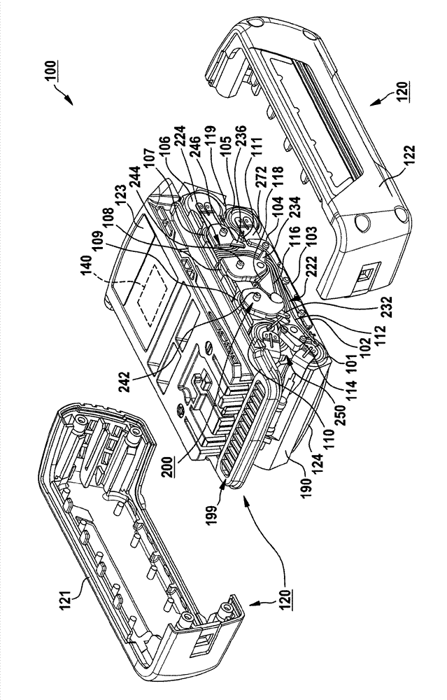
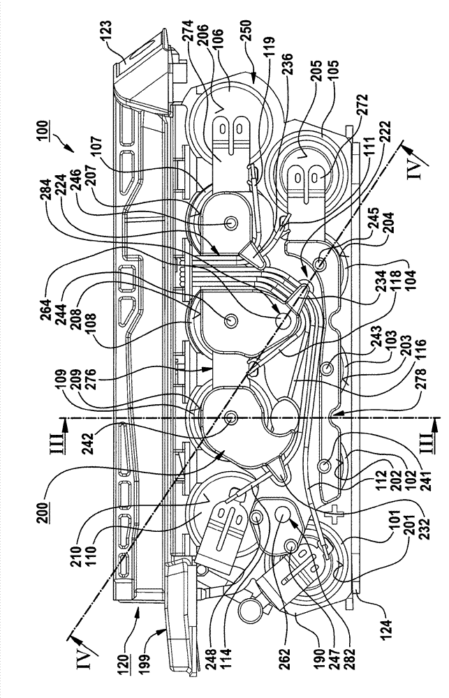
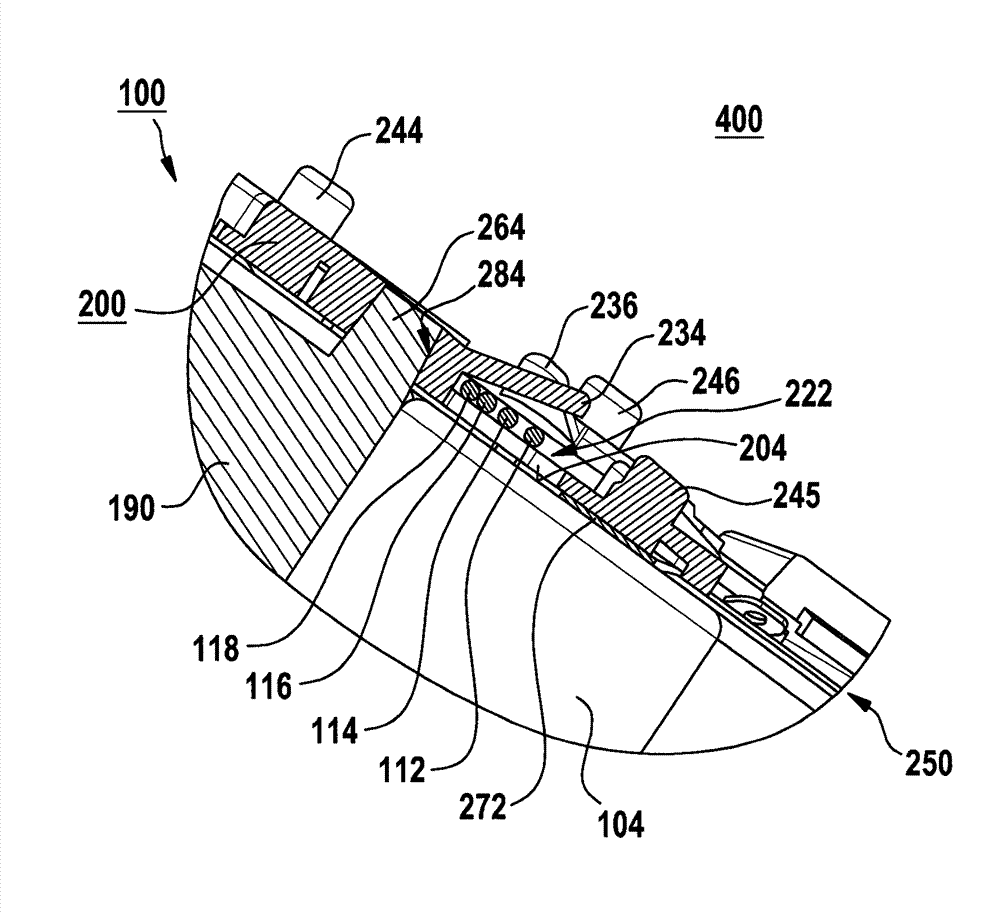
[0033] According to one specific embodiment, at least in the region of the end faces of the at least one battery cell, at least one wire is fastened, for example by soldering, via which the at least one battery cell is connected to the electronic component 140 . Here, the electric wires can be fastened not only directly to the end face, but also to a unit connector fastened to the end face. For example, six wires 111 , 112 , 114 , 116 , 118 , 119 are provided, wherein, for example, wire 114 is fastened in the region of the end face ( 210 in FIG. 2 ) of battery cell 110 , and wire 111 is fastened in such a way that battery cell 104 , 105 end faces ( 204 , 205 in FIG. 2 ) are connected to each other on the unit connector 272 .

[0034] By way of example, at least part of the battery cells 101 , 102 , 103 , 104 , 105 , 106 , 107 , 108 , 109 , 110 are supported in a housing filling structure 190 that is preferably suitable for conducting heat. The housing filling structure surrou...


PUM


Abstract

In an accumulator having multiple accumulator cells situated in an accumulator housing, the end faces of the accumulator cells which face a specified housing section forming an end face plane, and at least one electrical line being fastened to at least one end face of at least one accumulator cell, the at least one accumulator cell being connected via the electrical line to an electronic component associated with the accumulator, at least one line routing element is situated, at least in sections, in the area of the end face plane between the end faces facing the specified housing section and the housing section, the line routing element having at least one guide element for guiding the at least one electrical line.

Description

technical field [0001] The invention relates to a battery having a plurality of battery cells arranged in a battery housing, the end faces of which face a predetermined housing section forming an end layer, wherein at least one end face of at least one battery cell is fastened to at least one A line via which at least one battery cell is connected to electronic components associated with the battery. Background technique [0002] Batteries are known from the prior art which have a plurality of battery cells which are electrically conductively connected to one another by so-called cell connectors and which are connected in groups or modules and are therefore often also referred to as “battery packs”. In this case, the individual battery cells are usually welded to the cell connectors, for example by electronic spot welding. The cell connectors are arranged at least partially on the end faces of the battery cells and can be connected via electrical lines to electronic compone...

Claims


Application Information

Patent Timeline
Patent Type & Authority Applications(China)
IPC IPC(8): H01M2/20H01M2/10H01M10/42H01M50/50H01M50/503
CPCY02E60/12H01M10/4207H01M2/105H01M2/202H01M2/06H01M2/10H01M2/20G01R31/3658H01M10/425H01M10/42Y02E60/10H01M50/213H01M50/50H01M50/503
Inventor W.马蒂亚斯T.克德J.鲍姆加特纳
Owner ROBERT BOSCH GMBH
Why Eureka
Try Eureka