Multi-functional operation device for drawers of novel complete equipment
A technology for complete sets of equipment and operating devices, applied in switchgear, pull-out switch cabinets, electrical components, etc., can solve the problems of inconvenient installation and electrical wiring, cumbersome operation, and large operating torque.
- Summary
- Abstract
- Description
- Claims
- Application Information
AI Technical Summary
Problems solved by technology
Method used
Image
Examples
Embodiment 1
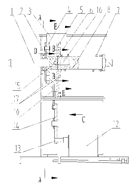
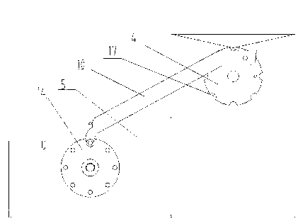
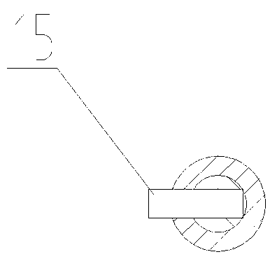
[0015] Embodiment 1, a new type of complete equipment drawer multifunctional operating device, refer to Figure 1-Figure 6 , the moving shaft 1 is movably installed in the upper sleeve of the frame 2, the front end of the moving shaft 1 is set with a positioning plate 4, the positioning plate 4 is connected to the turntable 14 installed below it through the connecting rod 10, and one end and the middle of the swing rod 11 Shafts are installed on the frame 2 and the rotating disk 14 respectively, so that the positioning plate 4, the connecting rod 10, the rotating disk 14, the moving rotating shaft 1, and the frame 2 form a four-bar linkage mechanism. 1. Go through the inner wall 5 of the frame and extend into the hollow front end of the circuit breaker control shaft 8. The front end of the circuit breaker control shaft 8 is fixed with a circuit breaker control shaft turntable 6, and the spring 7 is set on the circuit breaker control shaft turntable 6 and the frame 2. On the ci...
Embodiment 2
[0016] Embodiment 2, a new type of complete equipment drawer multifunctional operating device, refer to Figure 2-Figure 7 , on the basis of Embodiment 1, a limit screw 9 that limits the movement of the circuit breaker control shaft turntable 6 is provided in the frame 2, and the others are exactly the same as Embodiment 1.
[0017] When using the present invention, when the circuit breaker is in the opening position, the operating handle will automatically enter the moving shaft 1 when the drawer panel is closed, and the moving shaft 1 and the transmission pin 15 mounted on it can be pushed along the machine by pushing the operating handle. The positioning groove 16 of the inner wall 5 of the frame pushes the turntable 6 on the control shaft 8 of the circuit breaker to compress the spring 7 and enters the positioning groove of the control shaft 8 of the circuit breaker. Turning the operating handle clockwise can drive the control shaft 8 of the circuit breaker to rotate clockw...
PUM
 Abstract
Description
Claims
Application Information
 - R&D
- Intellectual Property
- Life Sciences
- Materials
- Tech Scout
- Unparalleled Data Quality
- Higher Quality Content
- 60% Fewer Hallucinations
Browse by: Latest US Patents, China's latest patents, Technical Efficacy Thesaurus, Application Domain, Technology Topic, Popular Technical Reports.
© 2025 PatSnap. All rights reserved.Legal|Privacy policy|Modern Slavery Act Transparency Statement|Sitemap|About US| Contact US: help@patsnap.com


