

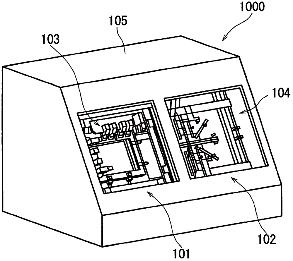
Lighting inspection device
A technology of inspection device and mounting table, which is applied in the field of lighting devices, can solve problems such as black spot defects of LCD panel pixel shading, and achieve the effect of simple deformation operation and avoiding interference
- Summary
- Abstract
- Description
- Claims
- Application Information
AI Technical Summary
Problems solved by technology
Method used
Image

Examples
Embodiment Construction
[0033] Embodiments of the present invention will be described below with reference to the drawings. In the following drawings, components having substantially the same functions are denoted by the same reference numerals for simplification of description. In addition, this invention is not limited to the following embodiment.
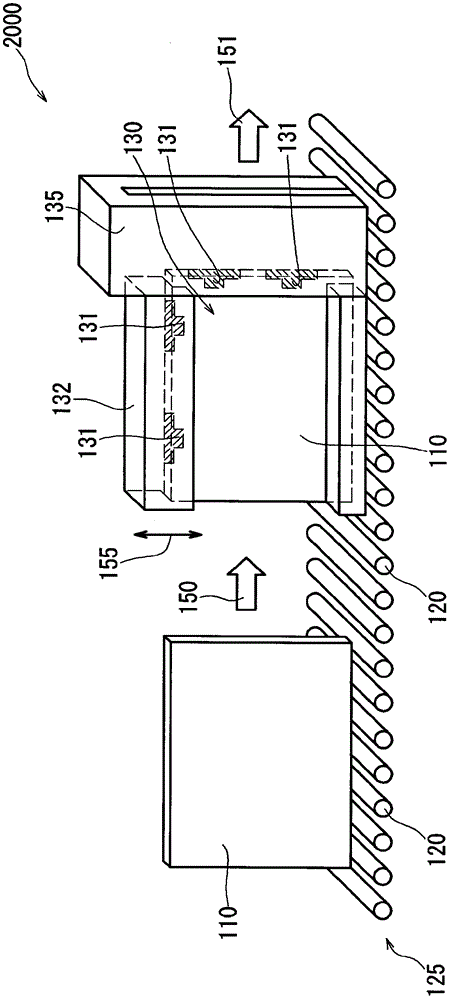
[0034] Figure 4 The configuration of a lighting inspection device 100 for inspecting lighting of a display panel is schematically shown. The lighting inspection device 100 of this embodiment includes: an inspection stage 30 on which a display panel (not shown) is placed;
[0035] The inspection stage 30 of the present embodiment includes: a column unit 35 ; and an upper unit 32 connected to the column unit 35 . The pillar unit 35 of the illustrated example extends in a vertical direction 90 , and the upper unit 32 extends in a direction perpendicular to the pillar unit 35 (ie, a horizontal direction). In addition, a lower unit 34 is provided below ...
PUM
 Abstract
Description
Claims
Application Information