Split pneumothorax puncture needle

A split-type, puncture needle technology, applied to puncture needles, trocars, guide needles, etc., can solve the problems of needle sheath removal, complicated operation, and increased patient pain, and achieves convenient operation, reduced pain, and fast puncture. Effect

Inactive Publication Date: 2013-01-23
CHONGQING INST OF MECHANICAL & ELECTRICAL ENG
View PDF2 Cites 4 Cited by
  • Summary
  • Abstract
  • Description
  • Claims
  • Application Information

AI Technical Summary

Problems solved by technology

Therefore, when the patient's thoracic cavity is drained, it is difficult for this structure to remove the needle cover from the drainage tube, thereby causing greater pain to the patient.
[0003] ZL200820023975.6 discloses a thoracentesis needle sheath. Although this kind of needle sheath can remove the needle sheath from the drainage tube, but because the needle sheath is connected by

Method used


Image

  • Split pneumothorax puncture needle
  • Split pneumothorax puncture needle
  • Split pneumothorax puncture needle

Examples


Embodiment 1

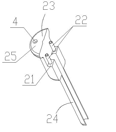
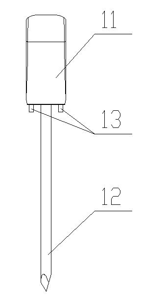
[0031] Example 1: Such as Figure 1 to Figure 5 As shown, a split thoracic puncture needle includes a needle core 1 and a needle sheath. The needle core 1 includes a needle core head 11 and a puncture part 12, and the needle cover is a split structure, and includes a first needle cover 2 and a second needle cover 3 that are matched with each other.

[0032] The first needle sheath 2 includes a first positioning portion 23 and a first guiding portion 24 of an integral structure. A first step surface 21 is provided on the first positioning portion 23, and two first positioning pins 22 are provided symmetrically along the axis of the needle sleeve on the first step surface 21.

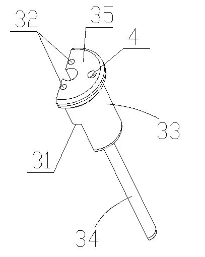
[0033] The second needle sheath 3 includes a second positioning portion 33 and a second guiding portion 34 that are integrally structured. The second positioning portion 33 is provided with a second step surface 31 which is matched with the first step surface 21, and the second positioning portion 33 is provi...

Embodiment 2

[0040] Example 2: Such as Figure 6 to Figure 12 As shown, the structure of this embodiment is basically the same as that of the first embodiment. The difference is that a first stop slope 26 is provided on the first guide portion 24, and a first stop slope 26 is provided on the second guide portion 34. 26 is a matching second stop slope 36; the first positioning portion 23 is provided with a third stop slope 27; the second positioning portion 33 is provided with a fourth stop slope that cooperates with the third stop slope 27 37.

[0041] Since the interface between the stop bevel and the first needle cover and the second needle cover may form a sharp acute angle, in order to prevent medical staff from being scratched when assembling and disassembling the puncture needle, the first stop bevel 26 and the first guide part The interface between 24 and the second guide portion 24 is rounded, and the second stop slope 36 is rounded with the interface between the second guide 34 and ...


PUM


Abstract

The invention discloses a split pneumothorax puncture needle, which comprises a needle core and a needle guard, wherein the needle core comprises a needle core head part and a puncture part; and the needle guard has a split structure, and comprises a first needle guard and a second needle guard which are matched with each other. Key points are that: the first needle guard comprises a first positioning part and a first guiding part which are integrated together; the first positioning part is provided with a first step surface; the first step surface is provided with at least one first positioning pin; the second needle guard comprises a second positioning part and a second guiding part which are integrated together; the second positioning part is provided with a second step surface which is matched with the first step surface; and the second positioning part is provided with a first positioning hole which corresponds to a first positioning pin on the second step surface. The split pneumothorax puncture needle is convenient to operate, and is rapid and accurate for puncturing; and after puncture is completed, the needle guard can be easily taken down from a drainage tube, so that pain of a patient can be reduced.

Description

Technical field [0001] The invention belongs to the technical field of medical equipment, and relates to a thoracic cavity drainage device, in particular to a thoracic cavity puncture needle. Background technique [0002] In the prior art, inserting a catheter into the thoracic cavity generally first cuts the skin, bluntly separates the subcutaneous tissue and muscle, and then punctures the puncture needle core covered with a needle sheath into the chest cavity from the incision, and then pulls out the needle core, The drainage tube is fed from the needle sheath into the chest cavity. Therefore, when the patient's thoracic cavity is drained, this structure is difficult to remove the needle cover from the drainage tube, which causes greater pain to the patient. [0003] ZL200820023975.6 discloses a thoracic puncture needle needle cover. Although this needle cover can take the needle cover out of the drainage tube, the needle cover is connected by a tube body with two lobes in cross...

Claims


Application Information

Patent Timeline
IPC IPC(8): A61M25/06A61B17/34
Inventor 吴俊刘东北熊静刘威
Owner CHONGQING INST OF MECHANICAL & ELECTRICAL ENG
Why Eureka
Try Eureka