Mechanism for snapping pin-point gate through stationary mold push plate for injection mold

A technology for injection molds and fixed molds, which is applied in the field of injection molds using fixed mold push plates to pull breakpoint gate mechanisms, which can solve the problems of low production efficiency, time-consuming, and inability to take them out at the same time

Active Publication Date: 2013-01-23
TAIZHOU KAIHUA AUTOMOBILE MOULD CO LTD
View PDF4 Cites 5 Cited by
  • Summary
  • Abstract
  • Description
  • Claims
  • Application Information

AI Technical Summary

Problems solved by technology

[0002] After the injection mold is finished injection molding, its waste and plastic parts will be connected together. In the prior art, workers will pry out the waste through copper rods, and because the waste is located above the cavity and the cavity insert, and is connected with the cavity and the cavity The inserts are close together

Method used


Image

  • Mechanism for snapping pin-point gate through stationary mold push plate for injection mold
  • Mechanism for snapping pin-point gate through stationary mold push plate for injection mold
  • Mechanism for snapping pin-point gate through stationary mold push plate for injection mold

Examples


Embodiment Construction

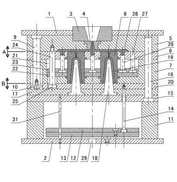
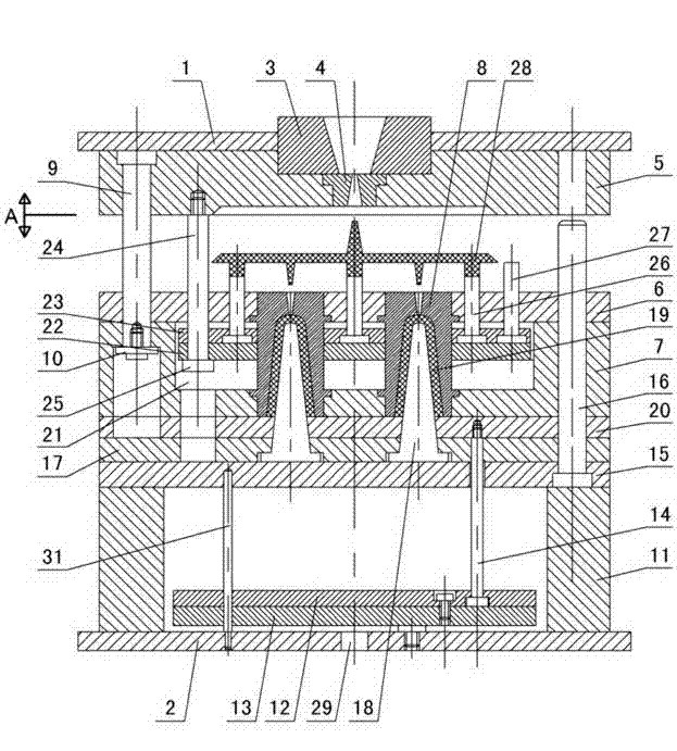
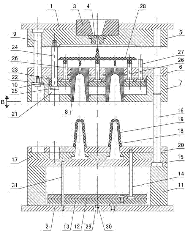
[0011] The invention relates to a gate mechanism for pulling a breaking point of an injection mold using a push plate of a fixed mold, such as figure 1 — Figure 4 As shown, it includes the upper doubler plate 1 and the lower doubler plate 2, the positioning ring 3 is installed in the upper doubler plate, the gate bushing 4 is connected under the positioning ring, the upper doubler plate 1 is connected with the runner plate 5, and the runner plate is connected under Cavity fixing plate 6, cavity plate 7 is connected under the cavity fixing plate, cavity insert 8 is fixed between the cavity plate and cavity fixing plate, fixed distance guide pillars 9 are set under the upper double plate 1, fixed distance guide pillars The baffle plate 10 is installed on the lower head, and the baffle plate is matched with the cavity plate 7. The mold feet 11 are installed on the lower double plate 2, the upper ejector plate 12 and the lower ejector plate 13 are arranged between the mold feet, ...


PUM


Abstract

The invention discloses a mechanism for snapping a pin-point gate through a stationary mold push plate for an injection mold, wherein the mechanism comprises an upper compound plate and a lower compound plate, a runner plate is connected below the upper compound plate, a mold cavity fixing plate is connected below the runner plate, a mold cavity plate is connected below the mold cavity fixing plate, a mold cavity embedding block is fixed between the mold cavity plate and the mold cavity fixing plate, a fixed distance guide post is arranged below the upper compound plate, a baffle is installed below the fixed distance guide post to be matched with the mold cavity plate, an upper thimble plate and a lower thimble plate are arranged between mold pins installed on the lower compound plate, a discharging push rod is installed between the upper thimble plate and the lower thimble plate, a punch hole is formed in the lower compound plate, an injector mandril passes through the punch hole to contact with the lower thimble plate, a plastic element is arranged between a mold core embedding block and the mold cavity embedding block fixed in the mold cavity fixing plate installed on a supporting plate, a discharging plate is arranged on the mold cavity fixing plate to be fixed with the discharging push rod, the mechanism is characterized in that a mold push plate and a stationary mold push plate fixing plate are arranged in a hollow cavity processed in the mold cavity plate, the disk-shaped large end of a fixed distance pull rod installed below the runner plate is in contact with the stationary mold push plate, a waste material mandril and a waste material jacking out a resetting rod are fixed in the stationary mold push plate fixing plate, and the waste material mandril is in contact with the waste material.

Description

technical field [0001] The invention relates to an injection mould, in particular to a gate mechanism at a breakpoint of the injection mould, which utilizes a push plate of a fixed mold. Background technique [0002] After the injection mold is finished injection molding, its waste and plastic parts will be connected together. In the prior art, workers will pry out the waste through copper rods, and because the waste is located above the cavity and the cavity insert, and is connected with the cavity and the cavity The inserts are close together, and the plastic part is located in the cavity. The two are blocked by the cavity and cannot be taken out at the same time. The two are connected by the waste between the gates of the cavity, so it is very laborious to pry the waste with a copper rod. Time-consuming, labor-intensive, low production efficiency, and easy to damage the mold. Contents of the invention [0003] The purpose of the present invention is to overcome the sho...

Claims


Application Information

Patent Timeline
IPC IPC(8): B29C45/38
Inventor 梁正华
Owner TAIZHOU KAIHUA AUTOMOBILE MOULD CO LTD
Why Eureka
Try Eureka