Riding work machine

A technology for working machines and transmission mechanisms, applied in steering mechanisms, control devices, transportation and packaging, etc., can solve problems such as low installation freedom

Inactive Publication Date: 2013-01-23
HONDA MOTOR CO LTD
View PDF7 Cites 9 Cited by
  • Summary
  • Abstract
  • Description
  • Claims
  • Application Information

AI Technical Summary

Problems solved by technology

This means that there is very little free

Method used


Image

  • Riding work machine
  • Riding work machine
  • Riding work machine

Examples


Embodiment Construction

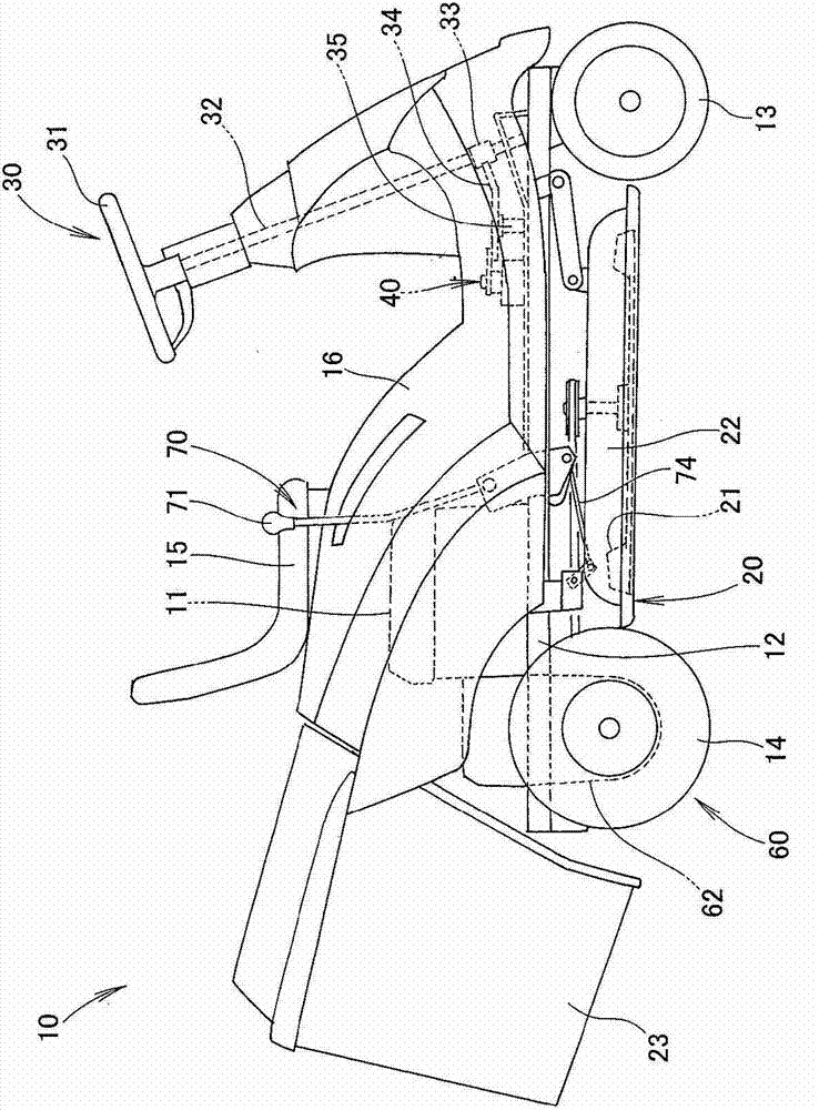
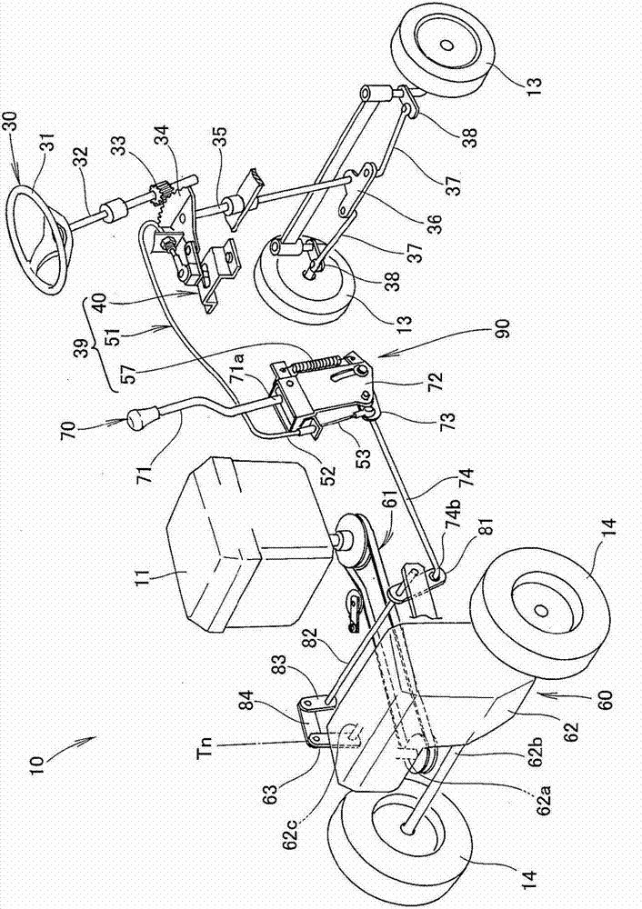
[0035] Such as figure 1 , 2 As shown, the riding work machine 10 includes a working system 20 , a steering system 30 and a traveling system 60 . The working machine 10 is driven by a single engine 11 together with a working system 20 . Specifically, the engine 11 drives the working system 20 through one belt, and drives the traveling system 60 through another belt. In this embodiment, the working system 20 includes a mowing unit.

[0036]The engine 11 is installed on the upper part of the rear part of the machine body 12 of the working machine 10 . The body 12 is equipped with left and right front wheels 13,13 and left and right rear wheels 14,14. The front wheels 13 and 13 are steered by a steering wheel 31 mounted on the front of the body 12 . The rear wheels 14, 14 are driving wheels driven by the output power of the engine 11.

[0037] Such as figure 1 As shown, the mowing part of the handling system 20 is arranged below the middle part of the machine body 12 and in...


PUM


Abstract

A riding work machine (10) comprises a steering wheel (31), an engine (11), a hydraulic stepless transmission mechanism (62) for transmitting power of the engine (11) to a driving wheel (14, 14), and a pivotable operation lever (71) for operating the hydraulic stepless transmission mechanism (62) to change the running speed of the work machine (10). A return mechanism for returning the hydraulic stepless transmission mechanism (62) to a position of reducing the running speed of the work machine (10) when the hydraulic stepless transmission mechanism (62) is operated by the operation lever (71) and the steering wheel (31) is turned is mounted at a base (71a) of the operation lever (71).

Description

technical field [0001] The invention relates to a ride-on working machine driven by an engine and capable of automatically reducing the traveling speed when turning. Background technique [0002] Recently, the steering system and the work system of ride-on work machines have been able to work in harmony with each other, so that the work machine can also work safely and efficiently while turning safely. As one of such working machines, agricultural machines are required to have sufficient durability to be able to be used under severe working conditions. In order to provide a work machine such as an agricultural machine with sufficient durability, in Japanese patent applications JP-A-51-42218 and JP-A-57-91414, there is disclosed a machine that does not require the use of an electric control system but only uses a mechanical The system can make the working machine automatically decelerate when the working machine turns. [0003] A ride-on work machine disclosed in Japanese P...

Claims


Application Information

Patent Timeline
IPC IPC(8): B62D15/00B60K17/06
Inventor 山本隆弘饭野启司市川胜久
Owner HONDA MOTOR CO LTD
Why Eureka
Try Eureka