Artificial shoulder joint prosthesis

A shoulder joint and prosthesis technology, applied in the field of artificial shoulder joint prosthesis, can solve the problems of poor anatomical adaptability, unable to satisfy the continuous adjustment of the prosthesis at the same time, unable to realize the anatomical reconstruction of the proximal humerus, etc., and achieve the effect of improving the accuracy

Active Publication Date: 2013-01-30
THE FIRST AFFILIATED HOSPITAL OF THIRD MILITARY MEDICAL UNIVERSITY OF PLA
View PDF8 Cites 9 Cited by
  • Summary
  • Abstract
  • Description
  • Claims
  • Application Information

AI Technical Summary

Problems solved by technology

The first-generation prosthesis is an integrated design with poor anatomical fit, and has been basically abandoned
At present, the prosthesis widely used clinically is the 2nd generation and 3rd generation prosthesis, and some use the 4th generation prosthesis. The previous prosthesis design cannot satisfy the continuous adjustment of the neck-shaft angle, torsion angle and eccentricity of the prosthesis at the same time. Therefore, the original anatomical structure of the proximal humerus cannot be well restored.
[0004] Patent 201120075330.9 discloses a proximal humerus shoulder joint prosthesis, which consists of a humerus ball head, a proximal humerus handle, a humerus intramedullary needle, and screws. Both are fixed on the connecting head by screws. The disadvantage is that the angle between the proximal humeral handle and the humeral ball head cannot be adjusted, and the anatomical reconstruction of the proximal humerus cannot be realized.

Method used


Image

  • Artificial shoulder joint prosthesis
  • Artificial shoulder joint prosthesis
  • Artificial shoulder joint prosthesis

Examples


Embodiment

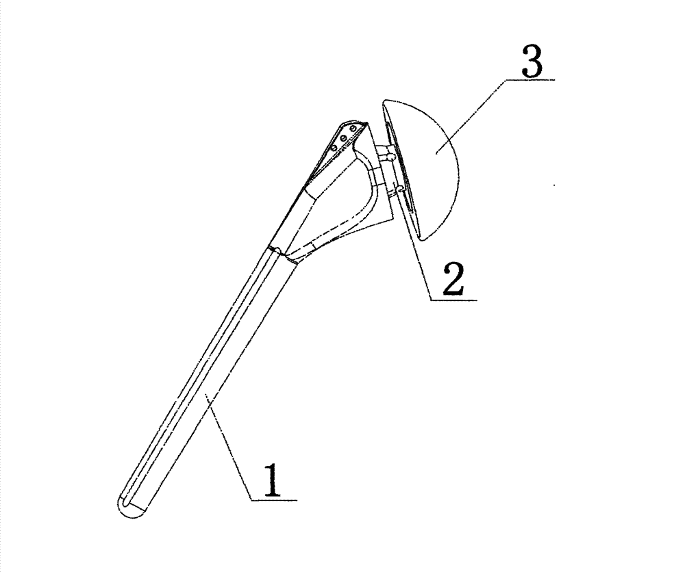
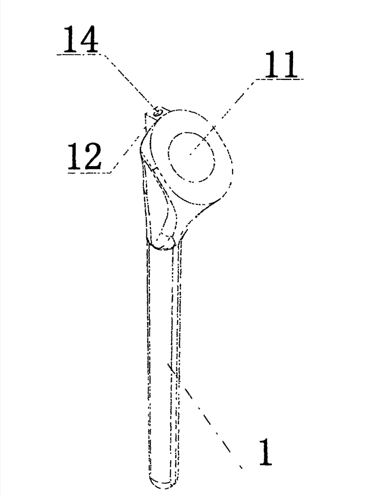
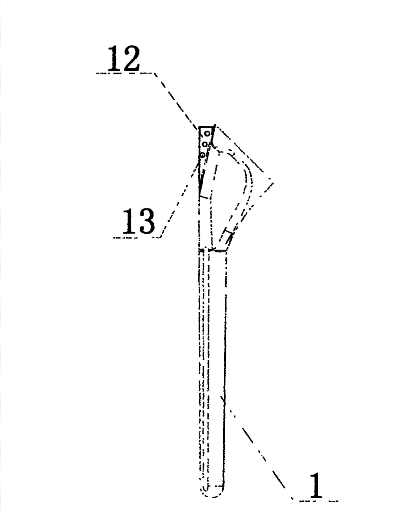
[0016] Embodiment: The metal materials used in the manufacture of the present invention are medical titanium and titanium alloys, or medical cobalt-chromium-molybdenum alloys. refer to figure 1 , figure 2 , image 3 , Figure 4 and Figure 5 , an artificial shoulder joint prosthesis, comprising a prosthesis stem 1, a connecting neck 2 and a prosthesis head 3, the upper end surface of the prosthesis stem 1 is consistent with the inclination angle of the patient's humerus osteotomy surface, and a ball socket 11 is arranged in the middle of the upper end surface , the back of the upper end surface is provided with a ridge 12, and the top surface of the ridge 12 is provided with a holding hole 14, and the holding hole 14 has an internal thread, which can be screwed in for the holder; there are three rotator cuff suture holes 13 on the side of the ridge 12, Used to suture the rotator cuff tendon.

[0017] The connecting neck 2 is an integrally formed connecting column 23, tra...


PUM


Abstract

The invention discloses an artificial shoulder joint prosthesis. The artificial shoulder joint prosthesis comprises a prosthesis handle, a connecting neck and a prosthesis head, wherein a ball socket is arranged on an upper end surface of the prosthesis handle; the connecting neck is provided with a connecting column, a tray and an expansion ball which are integrated into a whole from top to bottom; a convex column is arranged beside the connecting column on the tray; a ball body of the expansion ball is in a crack shape; the expansion ball and the ball socket are matched to form a spherical hinge structure; an expansion screw is screwed into the ball body of the expansion ball from a countersink part; the ball body of the expansion ball generates a frictional bond stress with the ball socket after being expanded, so as to fixedly connect the expansion ball with the prosthesis handle; the prosthesis head is a spherical crown body and comprises a bottom surface and a highly polished spherical surface; a connecting hole is eccentrically arranged in the bottom surface; a circle of adjusting holes are arranged at the periphery of the connecting hole; the connecting hole is in interference fit with the connecting column; and the convex column is inserted into the adjusting hole. According to the artificial shoulder joint prosthesis, a collodiaphyseal angle, a torsion angle and an eccentric distance of a humeral head prosthesis can be continuously adjusted in a certain range, a better individual anatomical matching property is achieved, and different medical demands can be met.

Description

technical field [0001] The invention relates to an artificial shoulder joint prosthesis, which belongs to the field of medical instruments. Background technique [0002] At present, artificial shoulder joint replacement has been widely used clinically, and has good curative effect on diseases such as shoulder osteoarthritis, rheumatoid arthritis, comminuted fracture of proximal humerus, avascular necrosis of humeral head, and shoulder malignant tumors. . [0003] The design of artificial shoulder prosthesis has gone through 4 generations. The first-generation prosthesis is an integrated design with poor anatomical fit, and has been basically abandoned. At present, the prosthesis widely used clinically is the 2nd generation and 3rd generation prosthesis, and some use the 4th generation prosthesis. The previous prosthesis design cannot satisfy the continuous adjustment of the neck-shaft angle, torsion angle and eccentricity of the prosthesis at the same time. Therefore, the...

Claims


Application Information

Patent Timeline
Patent Type & Authority Applications(China)
IPC IPC(8): A61F2/40
Inventor 汪华清唐康来周兵华胡超
Owner THE FIRST AFFILIATED HOSPITAL OF THIRD MILITARY MEDICAL UNIVERSITY OF PLA
Why Eureka
Try Eureka