
High-speed centrifugal atomization device

A technology of atomization device and high-speed centrifugation, applied in spray evaporation, evaporator accessories, etc., can solve the problems of damage, affecting the atomization plate, low production efficiency, etc., to achieve good dynamic balance stability, improve production efficiency, and dynamic balance stable effect

Active Publication Date: 2013-01-30
GUANGDONG ORIENT ZIRCONIC IND SCI & TECH CO LTD
View PDF6 Cites 1 Cited by
  • Summary
  • Abstract
  • Description
  • Claims
  • Application Information

AI Technical Summary

Problems solved by technology

[0003] Because the slurry injected into the atomizing disk exerts a unilateral force on the atomizing disk, which affects the dynamic balance of the atomizing disk; the slurry injected into the atomizing disk is easy to condense on the atomizing disk, which also affects the atomization The dynamic balance of the disc; at the same time, because the distance between the slurry distributor and the atomizing disc is very small, and the stainless steel slurry distributor has a high temperature due to the heat transfer between the shell and the backsplash to the slurry distributor The slurry on the lower surface will condense soon, causing friction with the atomizing disc, and also affecting the dynamic balance of the atomizing disc, which will cause the atomizing disc to lose its dynamic balance and be damaged under the condition of high-speed rotation, seriously Affect the efficiency and stability of equipment operation, frequent failures, and low production efficiency

Method used


Image

  • High-speed centrifugal atomization device
  • High-speed centrifugal atomization device

Examples


Embodiment Construction

[0013] Further description will be given below in conjunction with the accompanying drawings and preferred embodiments of the present invention.

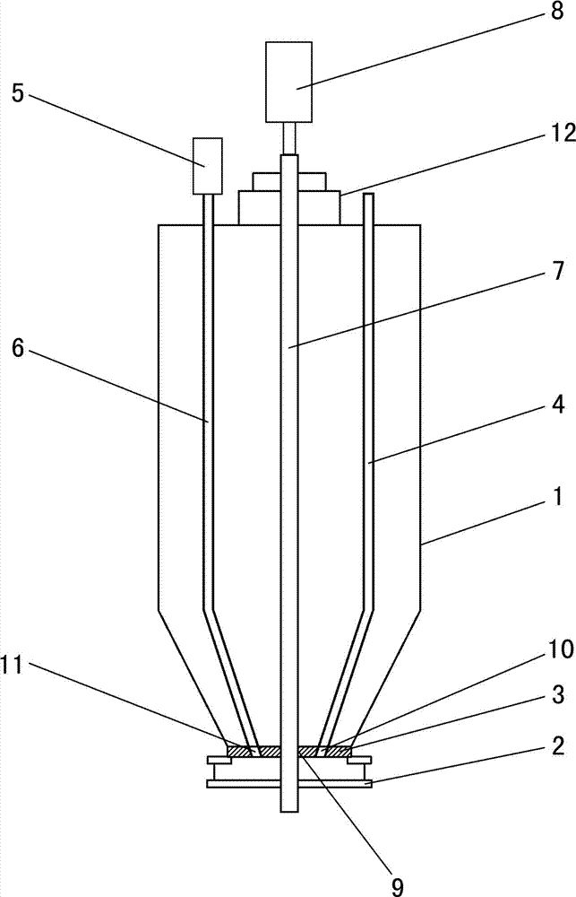
[0014] like figure 1 As shown, this high-speed centrifugal atomization device includes a housing 1, an atomizing disc 2, a slurry distributor 3, a material pipe 4, a gas injection device 5, an air pipe 6, a rotating shaft 7 and a motor 8; the slurry distributor 3. It is fixedly installed at the opening of the lower end of the housing 1. The slurry distributor 3 is provided with a shaft hole 9, a material hole 10 and an air hole 11. The air hole 11 and the material hole 10 are symmetrically arranged on both sides of the rotating shaft 7; the rotating shaft 7 is located in the shell In the body 1, the upper end of the rotating shaft 7 is rotatably installed on the top of the housing 1 through the bearing 12, and the lower end of the rotating shaft 7 is exposed outside the housing 1 through the shaft hole 9 on the slurry distributor 3;...


PUM


Abstract

The invention relates to a high-speed centrifugal atomization device, which comprises a shell, an atomization plate, a slurry dispenser, a material tube, a rotating shaft, a motor, an air injection device and an air tube. The slurry dispenser is provided with a material hole and an air hole, and the material hole and the air hole are symmetrically arranged in two sides of the rotating shaft; the lower end of the air tube is connected with the air hole, and the lower end of the material tube is connected with the material hole; and the air injection device is connected with the upper end of the air tube. Due to additional arrangement of the air injection device, the atomization plate is subject to acting forces produced by slurry injected into the atomization plate through the material hole and air sprayed to the atomization plate through the air hole, so better dynamic balance can be maintained by the atomization plate during rotation. Residual slurry on the atomization plate and slurry splashed back to the lower surface of the slurry dispenser can be blown away by the injected air, condensate of slurry on the atomization plate and the slurry dispenser can be reduced greatly, and the dynamic balance of the atomization plate can be made more stable. Therefore, the atomization plate has better stability of dynamic balance, the operation is stable, faults can be reduced, and the production efficiency can be increased.

Description

technical field [0001] The invention relates to an atomizing device, in particular to a high-speed centrifugal atomizing device used in the production process of composite zirconia spray drying. Background technique [0002] At present, the high-speed centrifugal atomization device used in the production process of composite zirconia spray drying generally includes a housing, an atomizing disc, a slurry distributor, a material pipe, a rotating shaft and a motor; the slurry distributor is fixedly installed at the lower end of the housing At the opening, the slurry distributor is provided with a shaft hole and a material hole; the rotating shaft is in the housing, the upper end of the rotating shaft can be rotated (usually through a bearing) and installed on the upper part of the housing, and the lower end of the rotating shaft passes through the shaft on the slurry distributor. The hole is exposed outside the shell, the atomizing disc is fixedly installed on the lower end of ...

Claims


Application Information

Patent Timeline
Patent Type & Authority Applications(China)
IPC IPC(8): B01D1/18B01D1/30
Inventor 许映波王树泉陈桐德许小军黄超华吴锦鹏赖建辉
Owner GUANGDONG ORIENT ZIRCONIC IND SCI & TECH CO LTD
Learn More