
Printer and paper turning mechanism for same

A printer and paper-turning technology, which is applied in printing devices, printing, etc., can solve the problems of blurred printing on the second side and affect the printing effect, and achieve the effect of improving quality

Inactive Publication Date: 2013-01-30
HONG FU JIN PRECISION IND (SHENZHEN) CO LTD +1
View PDF0 Cites 1 Cited by
  • Summary
  • Abstract
  • Description
  • Claims
  • Application Information

AI Technical Summary

Problems solved by technology

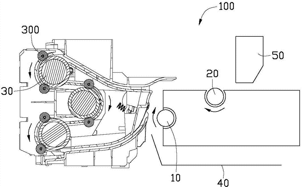
[0003] The above-mentioned printer has the following problem: when the paper turning is completed, the front end of the paper enters the position of the print roller 20, and the tail of the paper still partially remains in the turning mechanism 30, and the turning mechanism 30 stops rotating so that The end of the paper is clamped between the roller of the paper turning mechanism 30 and its corresponding auxiliary roller 300, and the paper can only be pulled out of the paper turning mechanism 30 by the pulling force of the printing roller 20 before entering the inkjet head 50 for printing. In the process of pulling the paper out of the paper turning mechanism 30, not only will the indentation of the paper turning mechanism 30 be left, but the insufficient pulling force of the printing roller 20 will also cause the printing on the second side to be blurred, which will affect the printing effect.

Method used


Image

  • Printer and paper turning mechanism for same
  • Printer and paper turning mechanism for same
  • Printer and paper turning mechanism for same

Examples


Embodiment Construction

[0016] The paper turning mechanism and the printer in the printer of the present invention will be further described in detail below in conjunction with the accompanying drawings.

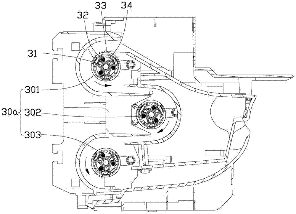
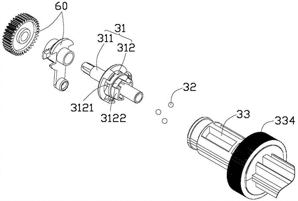
[0017] The present invention is aimed at figure 1 A modification of the paper turning mechanism 30 in the printer 100 is shown. figure 2 It is a schematic cross-sectional view of the paper turning mechanism 30a in one embodiment of the present invention. In this embodiment, the paper turning mechanism 30 a includes a first roller 301 , a second roller 302 and a third roller 303 . The paper feeding roller 10, the printing roller 20 and the first, second and third rollers 301-303 in the paper turning mechanism 30a are driven by the same motor (not shown) inside the printer 100 to rotate. The specific structural relationship Refer to below for Figure 2-4 description of.

[0018] When printing the first side, the motor drives the feed roller 10 and print roller 20 along the figure 1 Rotate clock...


PUM


Abstract

Disclosed is a paper turning mechanism for a printer. At least one roller positioned at a paper outlet end of the paper turning mechanism comprises a driving component, a plurality of driving balls and a paper delivery roll. A containing cavity is reserved at one end of the paper delivery roll, and a plurality of containing grooves are arranged on the side wall of the containing cavity. The driving component comprises a plurality of blades, recesses are formed among adjacent blades, the driving component is contained in the containing cavity, multiple containing spaces are respectively formed between the recesses and the side wall of the containing cavity, and the driving balls are contained in the containing spaces and capable of moving therein. When the driving component is driven to rotate in the containing cavity along a preset direction, the driving balls are driven to move by the blades. When being driven to move into the containing grooves, the driving balls are limited by the containing grooves and incapable of moving, so as to transmit driving force of the blades to the paper delivery roll and drive the paper delivery roll to rotate along with the driving component. When the driving component stops rotating, the paper delivery roll is capable of continuously rotating relative to the driving component along the preset direction under action of friction force between the tail end of a paper sheet and the paper delivery roll.

Description

technical field [0001] The invention relates to a paper turning mechanism for a printer and the printer. Background technique [0002] Such as figure 1 As shown, the current printer 100 with double-sided printing function generally includes a paper feeding roller 10 , a printing roller 20 , a paper turning mechanism 30 , a paper tray 40 and an inkjet head 50 . Wherein, the paper feeding roller 10, printing roller 20 and the paper turning mechanism 30 are driven by the same motor, when the printing roller 20 rotates clockwise as shown in the figure under the drive of the motor, the turning mechanism The roller in 30 is in a static state. When the motor counter-drives the printing roller 20 to rotate in the counterclockwise direction, the roller in the turning mechanism 30 will move along under the drive of the motor. figure 1 Turn in the direction indicated by the arrow. When performing double-sided printing, the paper is first sent from the input tray 40 to the position o...

Claims


Application Information

Patent Timeline
Patent Type & Authority Applications(China)
IPC IPC(8): B41J13/00
Inventor 吴昌修
Owner HONG FU JIN PRECISION IND (SHENZHEN) CO LTD
Learn More