pneumatic tire

A technology of pneumatic tires and tires, which is applied to the reinforcement layer of pneumatic tires, tire parts, tire edges, etc., which can solve the problems of easy increase of tire displacement and peeling, and achieve the effect of improving high-speed durability and suppressing peeling

Inactive Publication Date: 2016-06-08
SUMITOMO RUBBER IND LTD
View PDF6 Cites 0 Cited by
  • Summary
  • Abstract
  • Description
  • Claims
  • Application Information

AI Technical Summary

Problems solved by technology

[0003] However, although the conventional split ply d is sandwiched by the belt plies f1 and f2 arranged inside and outside the split ply d in the tire radial direction, there is a problem that the tire axis is damaged due to the missing part e in the center when driving at high speed. The upward displacement tends to increase, thus making it easy to peel off from the belt cords f1, f2

Method used


Image

  • pneumatic tire
  • pneumatic tire
  • pneumatic tire

Examples


Embodiment

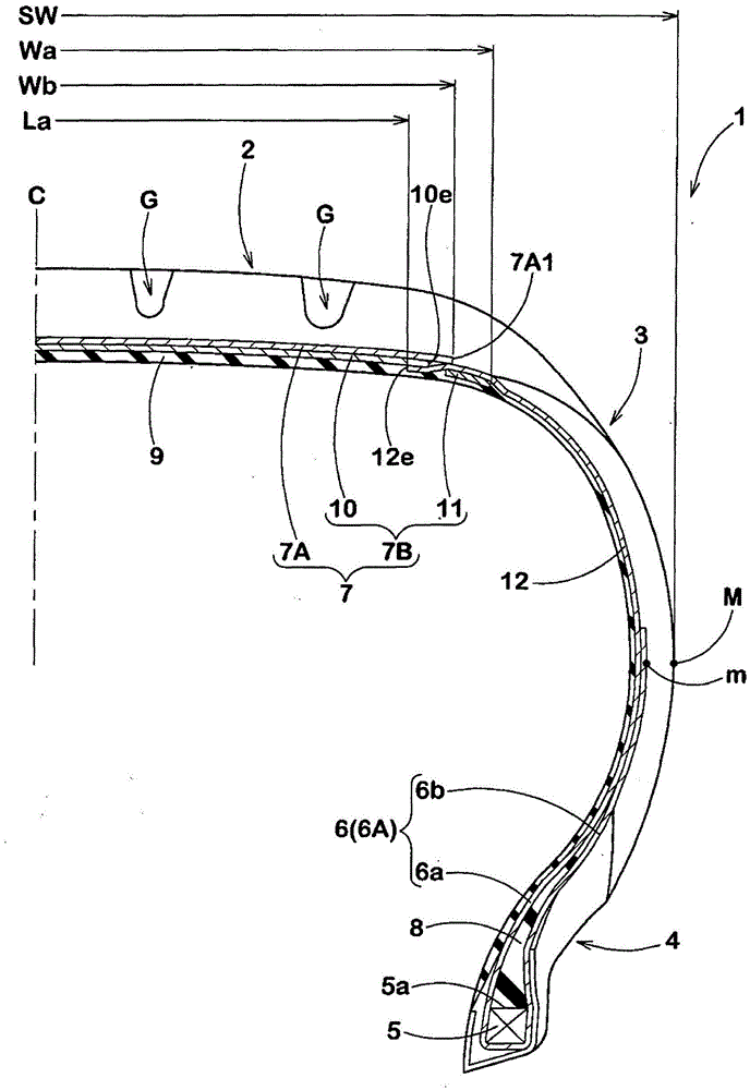
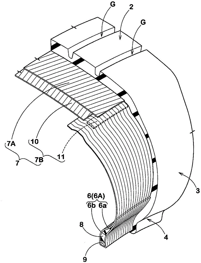
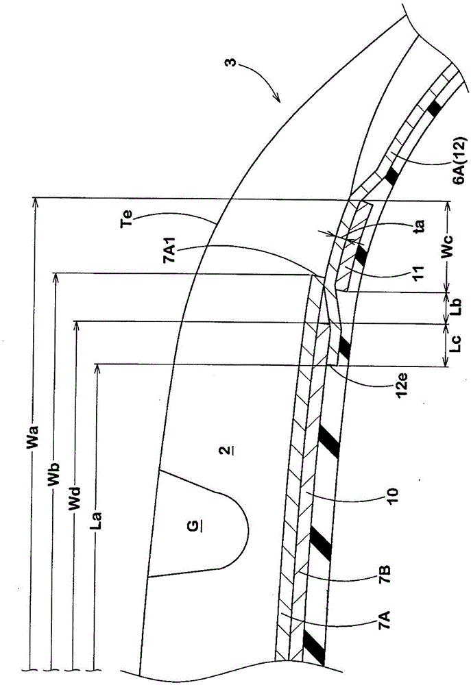
[0039] In order to confirm the effect of the present invention, based on the specifications of Table 1, a product formed as figure 1 The basic structure shown, and the tire size is 195 / 65R15 passenger car tires, and various tests were carried out on it. In addition, the main specifications other than Table 1 are the same.

[0040] The test method is as follows.

[0041]

[0042] The mass of each tire was measured and expressed using an index with the reciprocal of Comparative Example 1 being 100. The higher the value, the better.

[0043]

[0044] Using a drum testing machine, assemble the rim of the test tire on a rim of 17×7JJ, and make 20 test tires with a diameter of 1.7m under the conditions of filling an internal pressure of 220kPa, a load of 4.5kN, and a speed of 60km / h. The tires were driven on the drum and the time to damage was measured for each tire. The results are represented by an index with the average value of the damage time in Comparative Example 1 b...


PUM


Abstract

The present invention provides a pneumatic tire to achieve both reduction in weight of the tire and improvement of high-speed durability. The pneumatic tire (1) comprises: a carcass (6) comprising at least one carcass ply (6A); a belted layer (7) comprising a first belt ply (7A) and a second belt ply (7B) disposed closer to an inner side of a radial direction of the tire. The second belt ply comprises: a central sheet (10) disposed on a central part of a tire tread; and a pair of outer sheets (11, 11) disposed a distance away from the central sheet to an outer side of the tire axial direction. The carcass ply comprises a pair of right and left split ply sheets (12, 12) which form a central region including the tire equator (C) to be a central missing shape. The split ply sheets point from the inner side of the tire radial direction of the central sheet (10) towards the outer side of the tire radial direction, passes between the central sheet and the outer sheet (11), and extends towards the outer side of the tire radial dirction of the outer sheets.

Description

technical field [0001] The present invention relates to a pneumatic tire with reduced weight and improved high-speed durability. Background technique [0002] In recent years, it has been desired to reduce the weight of pneumatic tires, improve riding comfort, and reduce fuel consumption. In order to achieve such light weight, such as Figure 5 As shown, there is proposed a pneumatic tire a provided with a carcass ply b composed of a pair of left and right divided plies d formed in a central region including the tire equator C in a missing shape. Such a carcass ply b can be reduced in weight by missing the central portion e. [0003] However, although the conventional split ply d is sandwiched by the belt plies f1 and f2 arranged inside and outside the split ply d in the tire radial direction, there is a problem that the tire axis is damaged due to the missing part e in the center when driving at high speed. The upward displacement tends to increase, and thus tends to be p...

Claims


Application Information

Patent Timeline
Patent Type & Authority Patents(China)
IPC IPC(8): B60C9/10B60C15/00
Inventor 楠本拓士
Owner SUMITOMO RUBBER IND LTD
Why Eureka
Try Eureka