Eureka AIR delivers breakthrough ideas for toughest innovation challenges, trusted by R&D personnel around the world.

Splitting and assembling structure and assembling connecting method of assembled type concrete frame-shear wall

A shear wall and concrete technology, applied in the direction of walls, building components, building structures, etc., can solve the problems of inconvenient construction, long lap length, too many roots, etc., and achieve high assembly rate, less sleeves, and low cost low effect

Active Publication Date: 2013-01-30
SHENYANG JIANZHU UNIVERSITY
View PDF5 Cites 50 Cited by
  • Summary
  • Abstract
  • Description
  • Claims
  • Application Information

AI Technical Summary

Problems solved by technology

The current practice of the prefabricated shear wall structure is that the vertical reinforcement of the upper and lower walls is butt jointed by sleeves or lapped by steel grout anchors with reserved holes, and the horizontal reinforcement of the left and right walls is lapped by cast-in-place belts. The main problem is that the vertical reinforcement is generally Double gluten, the number of roots is too many, the lap length is long, and it is not convenient for construction

Method used


Image

  • Splitting and assembling structure and assembling connecting method of assembled type concrete frame-shear wall
  • Splitting and assembling structure and assembling connecting method of assembled type concrete frame-shear wall
  • Splitting and assembling structure and assembling connecting method of assembled type concrete frame-shear wall

Examples


Embodiment approach

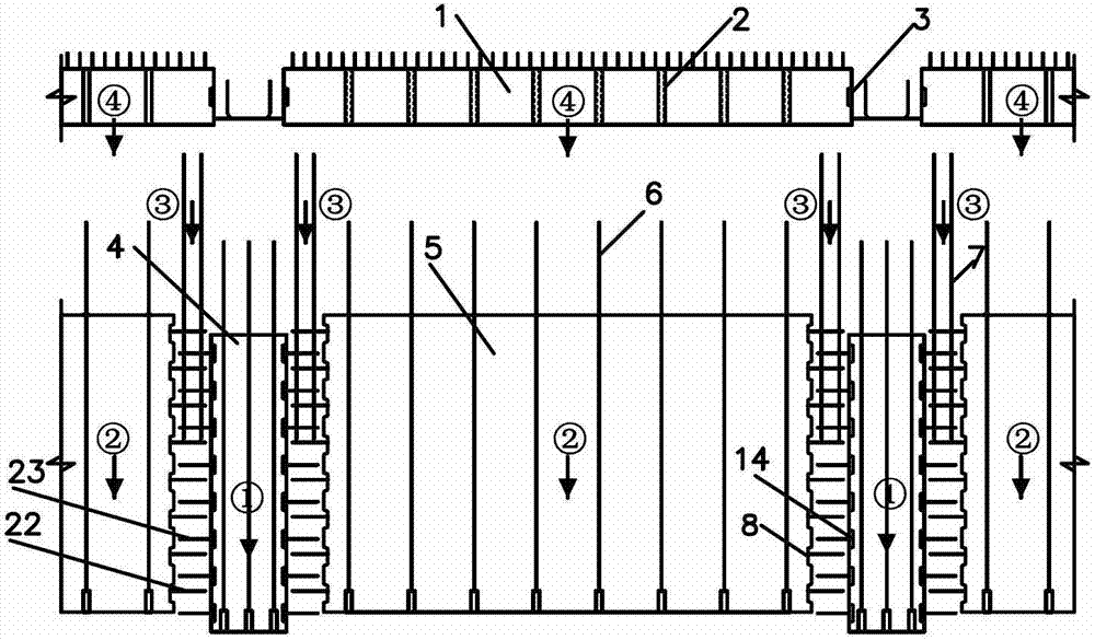
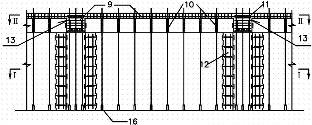
[0069] (1) The implementation scheme shown in Figure 1-3 is a composite beam method, and the prefabricated beam can also adopt a fully prefabricated method.

[0070] (2) The overlap between the beam end of the prefabricated beam and the column should not be less than 20mm, and the beam end face should be provided with a grooved shear key. The anchorage of the longitudinal reinforcement of the prefabricated beam in the core area of ​​the node can be in the form of a hook, or it can be paired with the beam on the other side of the node by a mechanical connection such as sleeve butt joint.

[0071] (3) In addition to the sleeve grouting butt joint method, the connection of the vertical reinforcement (core reinforcement) of the prefabricated shear wall can also adopt the reinforcement grout anchor lap joint with reserved holes.

[0072] (4) In the connection mode of the U-shaped connecting bars between the shear wall and adjacent columns, concealed columns can be formed as require...


PUM


Abstract

The invention relates to the field of concrete structures, in particular to a splitting and assembling structure and an assembling connecting method of an assembled type concrete frame-shear wall. The splitting and assembling structure comprises prefabricated pillars, prefabricated beams, prefabricated shear walls and cast-in-situ joints, wherein sleeves are embedded at the lower ends of the prefabricated pillars, mutually embedded with protruding reinforcing steel bar sections which extend from the upper ends of lower layer pillars and are integrally connected with the lower layer pillars by filling mortar; longitudinal prefabricated beam reinforcing steel bars extend into a joint core area to be anchored or connected with side beam ribs in a mechanical manner; a cast-in-situ zone is arranged between the prefabricated pillars and the prefabricated shear walls so as to carry out the connection of the embedded ribs of the pillars and the walls; and the embedded reinforcing steel bar sleeves at the lower ends of the prefabricated shear walls are mutually embedded with protruding reinforcing steel bar sections which extend upwards from the walls at the lower layer and are integrally connected with the walls at the lower layer by filling the mortar. The through connection of the vertical reinforcing steel bars of the share walls at the upper and lower layers is realized by filling the mortar into the through holes and the sleeves at the upper ends of the prefabricated shear walls and the prefabricated beams, so that the key problem that the vertical reinforcing steel bars of the share walls are hard to be continuous because of the isolation of the prefabricated beams is solved.

Description

【Technical field】 [0001] The invention relates to the field of prefabricated concrete structures, specifically a prefabricated assembly integral (hereinafter referred to as prefabricated) concrete frame-shear wall structure consisting of prefabricated columns, prefabricated beams and prefabricated shear walls. Connection structures, structures built by such split-and-assemble systems and connection structures, and assembly and connection methods. 【Background technique】 [0002] The existing technology of prefabricated concrete structures is mainly pure frame structure and pure shear wall structure, and the prefabricated concrete frame-shear wall structure composed of prefabricated columns, prefabricated beams and prefabricated shear walls has not yet been published. Compared with pure frame structure or pure shear wall structure, since the concrete frame-shear wall structure is a combination of wire and surface material, especially the shear wall is separated by beams and co...

Claims


Application Information

Patent Timeline
Patent Type & Authority Applications(China)
IPC IPC(8): E04B2/56E04B2/64E04G21/00
Inventor 赵唯坚
Owner SHENYANG JIANZHU UNIVERSITY
Why Eureka
Eureka Blog
Learn More