Two stage rotary compressor

A two-stage compressor, rotary technology, applied in the direction of rotary piston machinery, rotary piston pump, rotary piston/oscillating piston pump components, etc., can solve the problem of reduced compression efficiency, reduced bearing reliability, deflection To prevent problems such as increased pressure, to prevent the reduction of operating efficiency, reduce the loss of overcompression, and suppress the effect of pressure pulsation

Active Publication Date: 2013-01-30
MITSUBISHI ELECTRIC CORP
View PDF9 Cites 8 Cited by
  • Summary
  • Abstract
  • Description
  • Claims
  • Application Information

AI Technical Summary

Problems solved by technology

Therefore, the rotary two-stage compressor described in Patent Document 1 has a problem in that when the load of the refrigerant acts on the compression chamber, the degree of deflection of the drive shaft increases and the reliability of the bearing decreases.
[0014] In addition, in the rotary two-stage compressor described in Patent Document 2, the phase of the suction port of the high-stage compression part and the phase of the suction port of the low-stage compre

Method used


Image

  • Two stage rotary compressor
  • Two stage rotary compressor
  • Two stage rotary compressor

Examples


Embodiment approach

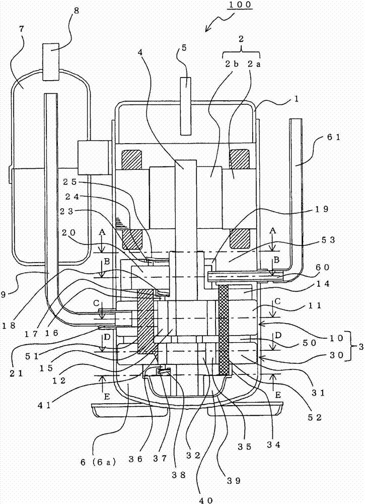
[0029] Hereinafter, the configuration of an example (two-stage compressor 100 ) of the rotary two-stage compressor of the present invention will be described.

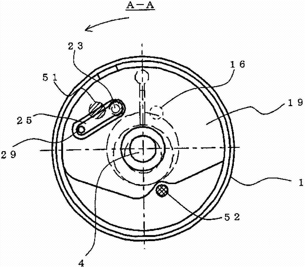
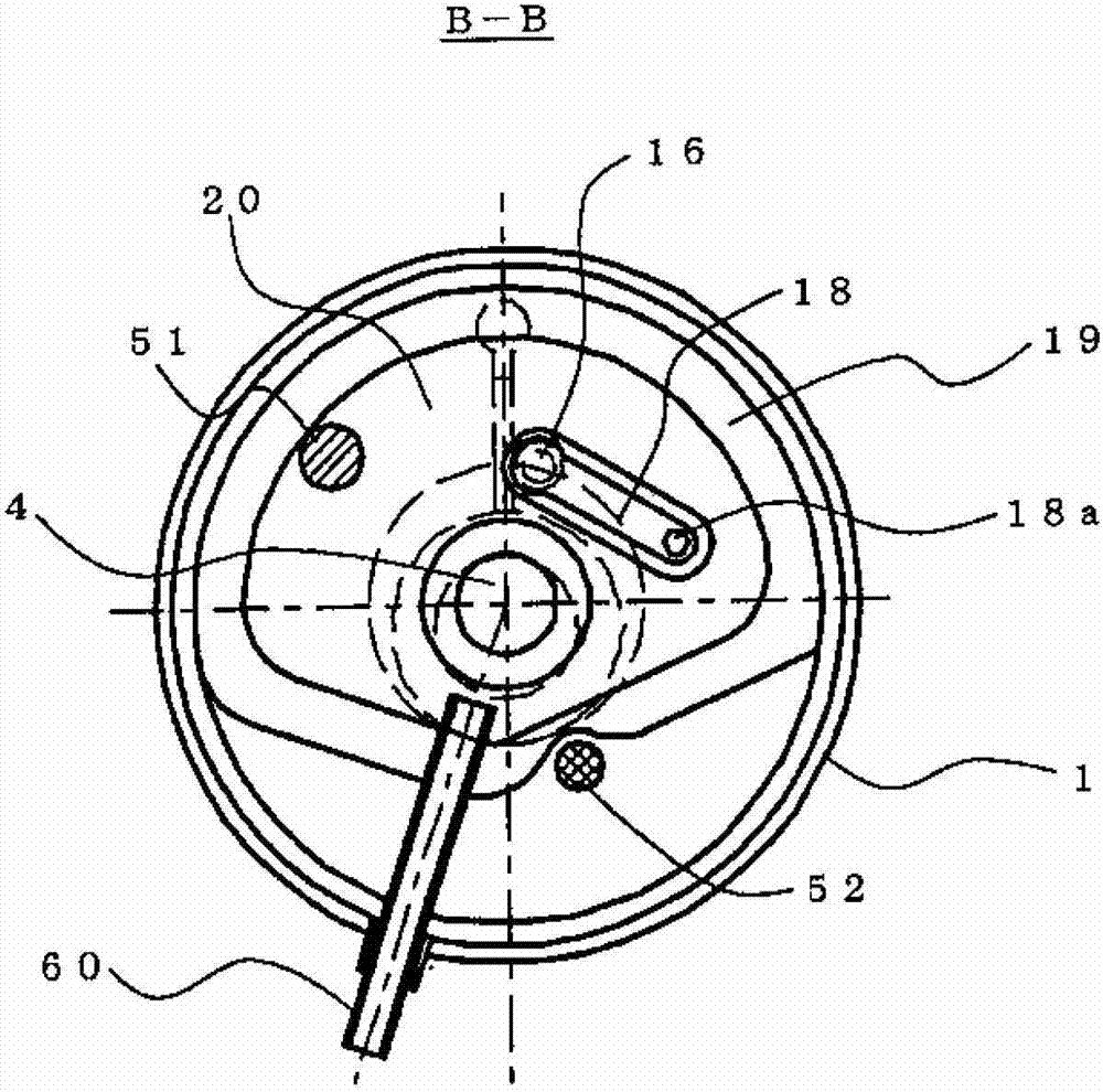
[0030] figure 1 It is a vertical cross-sectional view showing a two-stage compressor according to an embodiment of the present invention. in addition, figure 2 express figure 1 A-A sectional view of, image 3 express figure 1 The B-B sectional view, Figure 4 express figure 1 C-C cutaway view, Figure 5 express figure 1 D-D cutaway view, Figure 6 express figure 1 E-E cutaway view. in addition, figure 1 It is a diagram combining longitudinal sections cut at a plurality of cut positions for easy understanding of the structure of the two-stage compressor 100 . Therefore, the correct position of each structure observed from the top view or bottom view is Figure 2 ~ Figure 6 location shown.

[0031] In the two-stage compressor 100 of the present embodiment, two compression units (the low-stage compression u...


PUM


Abstract

The invention provides a two stage rotary compressor which can improve tracing ability of refrigerating fluid imported into an advanced compressing portion, restrain pressure fluctuation in intermediate flow paths, and prevent running efficiency from reducing in low load running. The two stage rotary compressor (100) of the internal high-pressure type includes a low stage cover (19) that covers a low stage outlet port (16) and forms a low stage discharge space (20) therein. Further, the two stage compressor (100) includes a compression mechanism (3) provided with an intermediate passage (51) that connects the low stage discharge space (20) and the high stage compression chamber (35) and a bypass mechanism (a bypass port (23), a bypass valve (24), and a bypass valve guard (25) in the low stage cover (19), in which the bypass mechanism opens when a load is smaller than a predetermined load and in which the bypass mechanism connects the low stage discharge space (20) and a discharge pressure space (53).

Description

technical field [0001] The invention relates to a rotary two-stage compressor having two compression sections. Background technique [0002] Conventionally, there is a rotary two-stage compressor in which two compression sections (a low-stage compression section and a high-stage compression section) are provided in a compression mechanism section, and the low-stage compression section and the high-stage compression section are connected in series. In such a rotary two-stage compressor, the low-stage compression unit compresses the refrigerant sucked in from the heat pump cycle to a predetermined pressure (reach pressure). The attained pressure is determined by the setting of the compression chamber volume of the low-stage compression section and the compression chamber volume of the high-stage compression section. The high-stage compression unit further compresses the refrigerant compressed by the low-stage compression unit. In addition, in the case of an internal high-pre...

Claims


Application Information

Patent Timeline
IPC IPC(8): F04C23/00F04C29/04
CPCF04C28/065F04C18/3564F04C23/008F04C28/26F04C23/001F04C18/356F04C23/00F04C29/12
Inventor 深谷笃义谷真男
Owner MITSUBISHI ELECTRIC CORP
Why Eureka
Try Eureka