Optical element adjusting module, projecting device and method for adjusting optical element

A technology for optical components and projection devices, applied in optical components, optics, projection devices, etc., can solve the problems of mirror angle deviation, projection device brightness and other optical quality effects, and achieve the effect of improving convenience and improving projection quality.

Inactive Publication Date: 2013-01-30
CORETRONIC
View PDF8 Cites 9 Cited by
  • Summary
  • Abstract
  • Description
  • Claims
  • Application Information

AI Technical Summary

Problems solved by technology

When the calculation of the optical path is not accurate enough or there are tolerances in the manufacture and assembly of the optical machine, it will cause the angle of the mirror to deviate, which will affect the brightness and other optical qualities of the projection device

Method used


Image

  • Optical element adjusting module, projecting device and method for adjusting optical element
  • Optical element adjusting module, projecting device and method for adjusting optical element
  • Optical element adjusting module, projecting device and method for adjusting optical element

Examples


Embodiment Construction

[0052] The aforementioned and other technical contents, features and effects of the present invention will be clearly presented in the following detailed descriptions of multiple embodiments with reference to the drawings. The directional terms mentioned in the following embodiments, such as "upper", "lower", "front", "rear", "left", "right", etc., are only referring to the directions of the attached drawings. Accordingly, the directional terms are used to illustrate, not to limit, the invention.

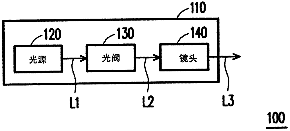
[0053] figure 1 It is a schematic diagram of a projection device according to an embodiment of the present invention. The projection device 100 of this embodiment includes an optical base 110 , a light source 120 , a light valve 130 and a lens 140 . The light source 120, the light valve 130 and the lens 140 are disposed on the optical base 110. The light source 120 is used to provide an illumination beam L1. The light valve 130 is, for example, a digital micromirror device (digita...


PUM


Abstract

The invention provides an optical element adjusting module, a projecting device and a method for adjusting an optical element. The optical element adjusting module comprises a frame body, a first adjusting element and a second adjusting element, wherein the frame body is provided with a connection part and a bare engine base connected with the projecting device through the connection part; a first axis and a second axis pass through the connection part; the optical element is arranged on the frame body; the first adjusting element is arranged on the frame body and is located on the first axis; when the first adjusting element is rotated, the first adjusting element drives the frame body to rotate relatively to the bare engine base by using the first axis as a center; the second adjusting element is connected with the base engine base and is screwed with the frame body; and when the second adjusting element is rotated, the second adjusting element drives the frame body to rotate relatively to the bare engine base by using the second axis as the center. Furthermore, the invention provides the projecting device with the optical element adjusting module and the method for adjusting the optical element.

Description

【Technical field】 [0001] The present invention relates to an adjustment module, an optical device and an adjustment method, and in particular relates to an optical element adjustment module, a projection device and an adjustment method for an optical element. 【Background technique】 [0002] A projection device is a display device for producing large-scale images. The imaging principle of the projection device is to convert the illumination beam generated by the light source into an image beam through a light valve, and then convert the image beam into a projection beam through a lens, and project it onto a screen or a wall. With the advancement of projection technology and the reduction of manufacturing costs, the use of projection devices has gradually expanded from commercial use to home use. [0003] Generally speaking, a reflector can be installed in the optical engine of the projection device, and the reflector is used to reflect the illumination beam emitted by the li...

Claims


Application Information

Patent Timeline
Patent Type & Authority Applications(China)
IPC IPC(8): G02B7/198G03B21/14G03B21/28G03B21/20
Inventor 武竹康陈昌湧
Owner CORETRONIC
Why Eureka
Try Eureka