Light following type high-efficiency photovoltaic power generation device and use method thereof
A photovoltaic power generation and light-following technology, which is applied in the field of high-efficiency light-following photovoltaic power generation devices, can solve problems such as insufficient power generation efficiency, achieve convenient disassembly, reduce maintenance, and ensure normal operation
- Summary
- Abstract
- Description
- Claims
- Application Information
AI Technical Summary
Problems solved by technology
Method used
Image
Examples
Embodiment 1
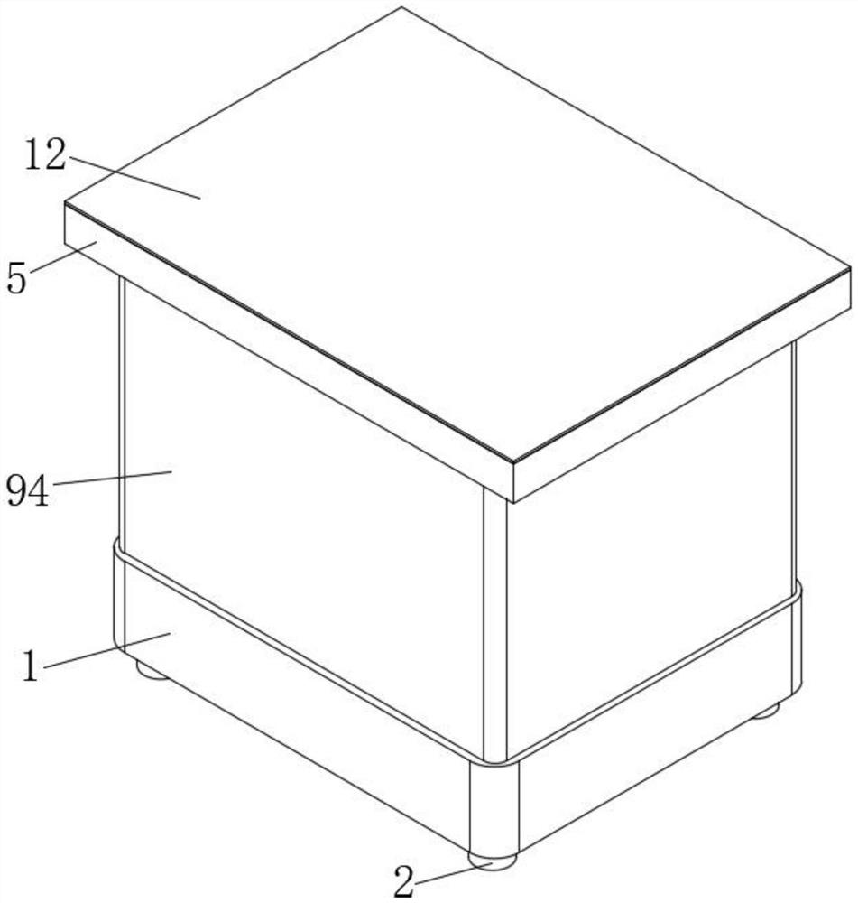
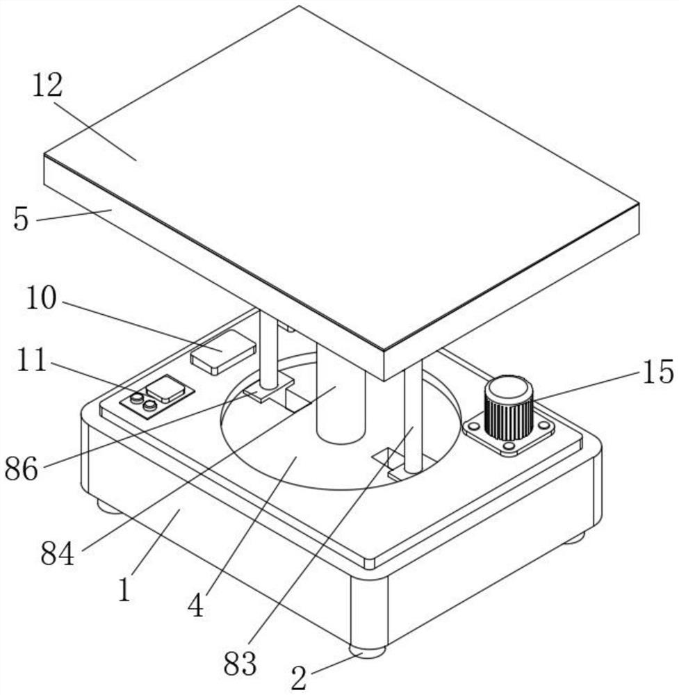
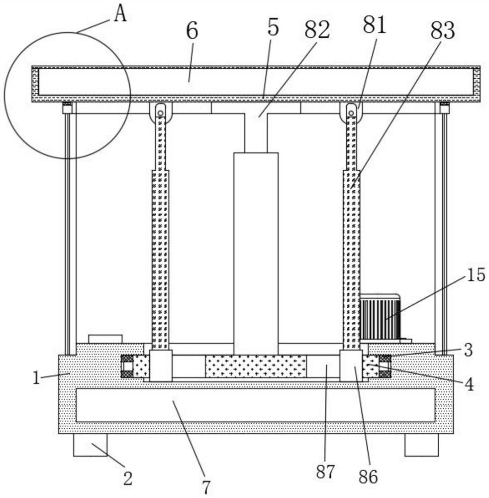
[0029] Embodiment 1: A light-following type high-efficiency photovoltaic power generation device, including a base plate 1, a light-following mechanism 8 and a protection mechanism 9;
[0030]Bottom plate 1: The rotating groove in the middle of the upper surface is connected with the turntable 4 through the rotation of the bearing 3, which is convenient for rotating the power generation components. The installation groove at the lower end of the bottom plate 1 is provided with a storage battery 7 to store electric energy. The lower surface of the bottom plate 1 The four corners are provided with support blocks 2 to provide support for the overall device. The left end of the upper surface of the base plate 1 is provided with a single-chip microcomputer 11. The input end of the single-chip microcomputer 11 is electrically connected to the output end of the battery 7 to control the start and stop of the light-tracking mechanism 8. The bottom plate The right end of 1 is provided wi...
Embodiment 2
[0035] The difference between this embodiment and Embodiment 1 is:
[0036] In this embodiment, the light tracking mechanism 8 includes an inclination sensor 82 and a support column 84, the support column 84 is arranged in the middle of the upper surface of the turntable 4, the upper end of the support column 84 is provided with an inclination sensor 82, and the detection end of the inclination sensor 82 is connected to the mounting bracket. The middle part of the lower surface of the plate 5 is fixedly connected, and the output end of the inclination sensor 82 is electrically connected to the input end of the single-chip microcomputer 11. The light-following mechanism 8 also includes a turret 81, an electric push rod 83, an I-shaped slider 86 and a chute 87, and the sliding Groove 87 is symmetrically arranged on the left and right ends of the upper surface of turntable 4, and the inside of chute 87 is all slidably connected with I-shaped slider 86, and the upper surface of I-s...
Embodiment 3
[0039] The difference between this embodiment and Embodiment 1 is:
[0040] In this embodiment, the protective mechanism 9 includes a magnet plate 91, a connecting frame 92, a dustproof bag 93 and a waterproof film 94. The magnet plate 91 is adsorbed on the outer edge of the lower surface of the mounting frame plate 5, and the lower surface of the magnet plate 91 is provided with a connection Frame 92, the lower surface of connecting frame 92 is respectively provided with dust-proof bag 93 and waterproof film 94, and the lower end of dust-proof bag 93 and waterproof film 94 is all fixedly connected with the outer edge of the upper surface of base plate 1.
[0041] Specifically, it is set in this way, during use, the magnet plate 91 is adsorbed on the lower surface of the mounting frame plate 5, so that the dustproof bag 93 and the waterproof film 94 cover the electrical appliances on the upper side of the bottom plate 1, so as to avoid the impact of external dust and water vapo...
PUM
 Abstract
Description
Claims
Application Information
 - R&D
- Intellectual Property
- Life Sciences
- Materials
- Tech Scout
- Unparalleled Data Quality
- Higher Quality Content
- 60% Fewer Hallucinations
Browse by: Latest US Patents, China's latest patents, Technical Efficacy Thesaurus, Application Domain, Technology Topic, Popular Technical Reports.
© 2025 PatSnap. All rights reserved.Legal|Privacy policy|Modern Slavery Act Transparency Statement|Sitemap|About US| Contact US: help@patsnap.com


