Stereoscopic imaging apparatus

A technology of stereoscopic imaging and equipment, applied in stereoscopic systems, stereophotography, image communication, etc., can solve the problems of heavy work, increased cost of stereoscopic imaging equipment, and overall large stereoscopic imaging equipment, and achieve the effect of reducing the size

Inactive Publication Date: 2013-01-30
SONY CORP
View PDF5 Cites 13 Cited by
  • Summary
  • Abstract
  • Description
  • Claims
  • Application Information

AI Technical Summary

Problems solved by technology

[0006] However, a stereoscopic imaging apparatus based on a beam splitter method in which two imaging units are mounted on a base called a rig is large and heavy as a whole.
Moreover, the edge of the half mirror should not appear in the field of view of each of the two imaging units, and the size of the half mirror needs to be large in proportion to the diameter of the lens in the imaging unit, which results in increase in cost
Also, in a stereoscopic imaging device in which the imaging unit is mounted on a stand, it is generally required to set the IAD, convergence angle and other parameters and alignment, and other adjustments every time an image is captured, resulting in extremely heavy work

Method used


Image

  • Stereoscopic imaging apparatus
  • Stereoscopic imaging apparatus
  • Stereoscopic imaging apparatus

Examples


Embodiment Construction

[0030] A stereoscopic imaging device according to an embodiment of the present disclosure will be described below. The description is performed in the following order.

[0031] 1. First Embodiment (Case where two image forming optical systems and imaging devices corresponding thereto are arranged such that their optical axes are parallel to each other)

[0032] 2. Second Embodiment (A Case Where Two Image Forming Optical Systems and Imaging Devices Corresponding Thereto Are Arranged Such That Their Optical Axes Intersect Each Other)

[0033] 3. Third Embodiment (Case where a plurality of image forming optical systems and imaging devices corresponding thereto are provided)

[0034]

[0035] [1-1. Example of Configuration of Stereoscopic Imaging Device]

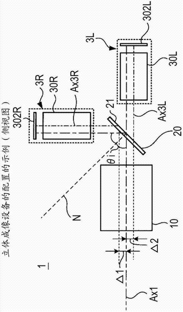
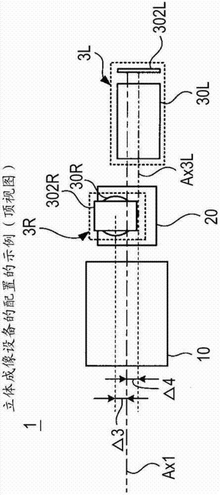
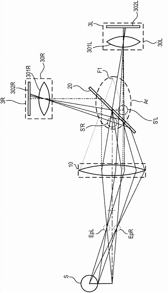
[0036] will first refer to Figure 1A with 1B An example of the configuration of the stereoscopic imaging device according to the first embodiment of the present disclosure is described through 5A and 5B. Figure 1A is a s...


PUM


Abstract

The invention discloses a stereoscopic imaging apparatus. The stereoscopic imaging apparatus includes: an objective optical system acquiring light rays emitted from a subject and guiding the light rays to a downstream component; a separation optical system having a partially reflective surface reflecting part of the light rays and transmitting part thereof; first image forming optical system disposed on a path along which the light rays reflected off the separation optical system travel and focusing the reflected light rays to form a parallax image; second image forming optical system disposed on a path along which the light rays passing through the separation optical system travel and focusing the transmitted light rays to form a parallax image; a first imaging device converting the parallax image formed by the first image forming optical system into an image signal; and a second imaging device converting the parallax image formed by the second image forming optical system into an image signal.

Description

technical field [0001] The present disclosure relates to stereoscopic imaging devices that capture stereoscopic images, and in particular to techniques for reducing the distance between two lenses used to capture stereoscopic video images. Background technique [0002] In recent years, cameras (stereoscopic imaging devices) capable of capturing 3D (stereoscopic) video images have been increasingly desired. One example of known stereoscopic imaging devices is based on a side-by-side approach, where two cameras are arranged such that the lens base lines of the cameras are parallel to each other (parallel two-lens approach). This type of stereoscopic imaging device is suitable for imaging with a long baseline length (IAD: Inter-Axis Distance), for example at least 65 mm, or for imaging distant objects. [0003] On the other hand, in order to capture images of nearby objects, the baseline length (hereinafter referred to as "IAD") needs to be a short length ranging from about 10...

Claims


Application Information

Patent Timeline
Patent Type & Authority Applications(China)
IPC IPC(8): G03B35/08G02B27/22H04N13/02
CPCG02B27/22G03B35/10H04N13/02G02B27/144H04N13/0239G03B35/08H04N13/239
Inventor 山田正裕青木直
Owner SONY CORP
Why Eureka
Try Eureka