
Control method and control device for display device backlight

A technology for a display device and a control device, applied to static indicators, instruments, etc., can solve problems such as noise or water ripples in liquid crystal displays, and achieve the effect of avoiding noise or water ripples and avoiding large fluctuations in initial brightness.

Active Publication Date: 2015-12-02
HEFEI BOE OPTOELECTRONICS TECH +1
View PDF5 Cites 0 Cited by
  • Summary
  • Abstract
  • Description
  • Claims
  • Application Information

AI Technical Summary

Problems solved by technology

However, this brightness adjustment method causes the brightness of the backlight source to change significantly in each PWM cycle, which may easily lead to poor display conditions such as noise or water ripples on the LCD during actual use.

Method used


Image

  • Control method and control device for display device backlight
  • Control method and control device for display device backlight
  • Control method and control device for display device backlight

Examples


Embodiment Construction

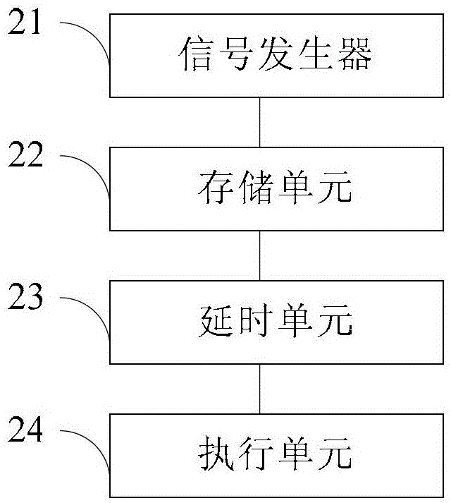
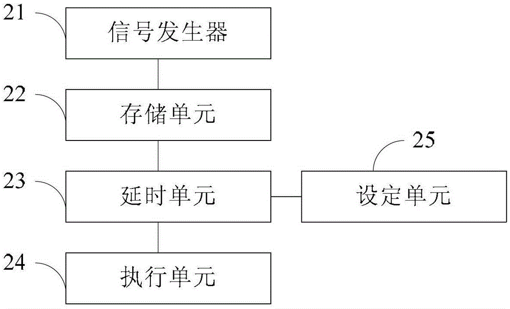
[0034] In order for those skilled in the art to better understand the technical solution of the present invention, the method for controlling the backlight source of the display device and the control device provided by the present invention will be described in detail below with reference to the accompanying drawings.

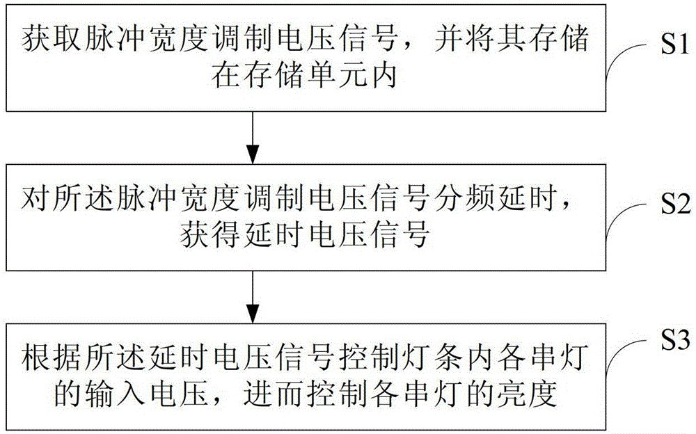
[0035] This embodiment provides a method for controlling the backlight source of a display device, which is a control method proposed for the light bars that constitute the backlight source, such as figure 1 As shown, it is a flowchart of a method for controlling a backlight source of a display device according to an embodiment of the present invention. The control method includes the following steps:

[0036] Step S1, acquiring a pulse width modulated voltage signal and storing it in a storage unit.

[0037] In step S1, the pulse width modulation voltage signal may be provided by an external circuit, or provided by other signal generators provided in the bac...


PUM


Abstract

The invention provides a control method and device of a backlight source of a display device and the display device. The control method comprises the following steps of: acquiring a pulse wide modulation voltage signal and storing the pulse width modulation voltage signal in a storage unit; carrying out frequency-division delaying on the pulse width modulation voltage signal to obtain a delaying voltage signal; and controlling input voltage of each string of lamps in lamp strips according to the delaying voltage signal to further control the brightness of each string of lamps. The control method of the backlight source of the display device can avoid great brightness fluctuation of the backlight source, thereby preventing the display device from generating adverse display conditions, such as noise point or water ripples.

Description

technical field [0001] The invention belongs to the field of display technology, and in particular relates to a control method and a control device for a backlight LED light bar of a display device. Background technique [0002] The LED light bar is often used as the backlight unit (BLU) of the liquid crystal display, and the brightness of the backlight is controlled by the pulse width modulation (PulseWidthModulation, PWM) signal, that is, the duty cycle of the PWM signal is adjusted within the period range to adjust the backlight. The brightness of the source. However, this brightness adjustment method causes the brightness of the backlight source to vary greatly in each PWM cycle, which may easily lead to poor display conditions such as noise or water ripples on the liquid crystal display during actual use. [0003] Therefore, there is an urgent need for those skilled in the art to develop a method for controlling the brightness of the backlight source, so as to avoid dr...

Claims


Application Information

Patent Timeline
Patent Type & Authority Patents(China)
IPC IPC(8): G09G3/34
Inventor 张文浩杨钰婷梁恒镇王慧
Owner HEFEI BOE OPTOELECTRONICS TECH
Learn More