Composite isopipe

A fusion and groove wall technology, applied in the direction of manufacturing tools, glass molding, glass manufacturing equipment, etc., can solve the problem of expensive integral forming body, achieve the effect of reducing average cost, reducing material consumption, and reducing weight load

Inactive Publication Date: 2013-01-30
CORNING INC
View PDF9 Cites 6 Cited by
  • Summary
  • Abstract
  • Description
  • Claims
  • Application Information

AI Technical Summary

Problems solved by technology

Furthermore, a monolithically formed body manufactured from a single material meeting all geometrical and shape stability requirements is very expensive, even at smaller sizes

Method used


Image

  • Composite isopipe
  • Composite isopipe
  • Composite isopipe

Examples


Embodiment

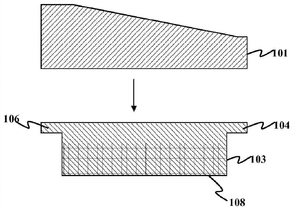
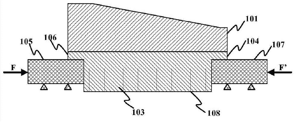
[0075] A composite isopipe containing an upper surface made of α-SiC operated at a root temperature of 1164°C, a weir temperature of 1221°C and a pressure F of 6000 psi Part 101 and lower part 103, 79 inches (2000 mm) long, fabricated from zircon. Figure 7 The estimated shape change at the interface between the upper and lower parts is shown. The data on the horizontal axis is the distance from the pressure end of the forming body (that is, the end of the forming body that is directly subjected to the pressure F relative to the glass melt inlet position), and the data on the vertical axis is the deviation rate, and the unit is micron / year . Curve 703 shows the shape of the lower surface of the upper part 101 , and curve 705 shows the shape of the upper surface of the lower part 103 . Distance 701 shows the maximum gap between the lower surface of upper part 101 and the upper surface of lower part 103 . As expected, there is essentially no shape change in the top piece as i...


PUM


Abstract

A fusion down-draw method for making a glass sheet using a forming body comprising an upper part (101) made of a first material and a lower part (103) made of a second material, where the first material has lower creep rate than the second material at the normal operating temperature of the forming body, and an fusion down-draw forming apparatus comprising such forming body. The invention is advantageous in that it solves the issues of internal stress and long-term creep issue of a unitary forming body made of a single material such as zircon.

Description

[0001] This application claims priority to US Provisional Application No. 61 / 349362, filed May 28, 2010. technical field [0002] The present invention relates to methods and apparatus for making glass sheets. In particular, the invention relates to a fusion down-draw process for making glass sheets and equipment used in the process. The invention is useful, for example, in the manufacture of high-precision glass substrates suitable for liquid crystal displays (LCDs). Background technique [0003] In various current major LCD devices, such as televisions, two high-precision glass sheets are used, one as the substrate of electronic circuit components, such as thin-film transistors (TFT), and the other as the substrate of color filters. Various techniques are available for manufacturing the high-precision optical glass substrate. A leading technique is the overflow fusion downdraw technique developed by Corning Incorporated, Corning, New York, U.S.A., which involves the use ...

Claims


Application Information

Patent Timeline
Patent Type & Authority Applications(China)
IPC IPC(8): C03B17/06C03B17/00C03C27/00
CPCC03B17/064C03B17/06C03C27/00
Inventor N·A·帕宁
Owner CORNING INC
Why Eureka
Try Eureka