Unlock instant, AI-driven research and patent intelligence for your innovation.

Video compression coding device and decoding device applied with motion compensation technique using selective reference frame, and method for determining selective reference frame for motion compensation

A reference image and motion compensation technology, applied in digital video signal modification, television, image communication, etc., can solve the problems of large differential image value and low compression efficiency, so as to increase compression efficiency, reduce time repeatability, and reduce bit generation effect

Inactive Publication Date: 2013-01-30
GALAXIA COMM
View PDF3 Cites 0 Cited by
  • Summary
  • Abstract
  • Description
  • Claims
  • Application Information

AI Technical Summary

Problems solved by technology

[0010] When motion estimation is performed on such an image, due to the motion blur generated in the reference image but not in the input image, or the absence of motion blur in the reference image but the motion blur in the input image In the case of , the difference image value will become larger, which will result in inefficient compression

Method used


Image

  • Video compression coding device and decoding device applied with motion compensation technique using selective reference frame, and method for determining selective reference frame for motion compensation
  • Video compression coding device and decoding device applied with motion compensation technique using selective reference frame, and method for determining selective reference frame for motion compensation
  • Video compression coding device and decoding device applied with motion compensation technique using selective reference frame, and method for determining selective reference frame for motion compensation

Examples


Embodiment Construction

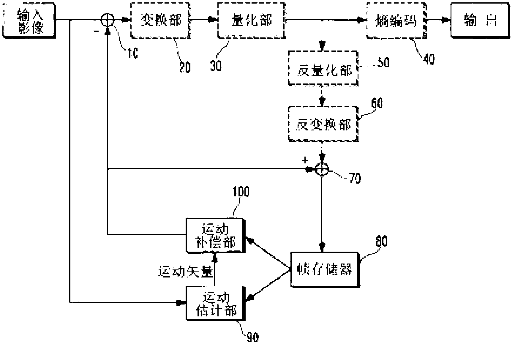
[0025] First, refer to the attached figure 2 In the embodiment shown in, the repetitive parts are processed with the same reference numerals to apply the video compression encoding device of the present invention to the motion compensation method using selective reference images as follows.

[0026] The video compression encoding device includes: a subtractor 10 for obtaining a difference signal between an input image and a motion-compensated image signal; and a transforming unit 20 for calculating the difference in the subtractor 10 according to a predetermined predetermined function The obtained difference signal is transformed; a quantization unit 30 that quantizes the image signal transformed by the transformation unit 20; an encoding unit 40 that encodes the image information quantized by the quantization unit 30; and a motion compensation unit that The video signal quantized by the quantizer 30 is subjected to inverse signal processing, thereby performing motion compensatio...


PUM


Abstract

The present invention relates to a method for generating a reference frame of a video CODEC for implementing motion compensation through motion estimation. In the case of each frame of resultant images photographed by a video apparatus, motion blurs of a certain direction are generated on a considerable number of frames due to the number of frames per second (FPS) of a camera, external factors such as shutter speed, movements of a photographing apparatus, shaking of the hand or the like, or to the movements or the like of an object to be photographed. When motion estimation is performed for said frames, if motion blurring occurs on reference frames and input frames do not have motion blurring, or if there is no motion blurring on the reference frames but the input frames have motion blurring, difference image values are set to be large, resulting in low compression efficiency. The present invention forms, on the reference frames, additional various reference frames, which have performed intentional motion blur and motion deblur filtering functions, and selects reference frames having low difference image data during the execution of the motion estimation as final reference frames among the original reference frames and the added various reference frames, thereby increasing compression efficiency.

Description

Technical field [0001] The present invention relates to a method for generating a reference frame (Reference Frame) of a video codec (CODEC) for embodying motion compensation through motion estimation. In more detail, it relates to, in addition to the existing reference images, additional production and The motion blur noise (Motion BlurNoise) reference image generated by the motion of the video input device such as the camera or the movement of things, etc. and the reference image for removing the motion blur noise, select the more efficient reference image from these multiple reference images, To achieve motion compensation to improve the compression efficiency of the video codec. Background technique [0002] Generally, video encoders using motion compensation methods through motion estimation, such as figure 1 As shown, it includes: a subtractor 10, which is used to obtain the difference signal between the input image and the motion-compensated image signal; and a transform u...

Claims


Application Information

Patent Timeline
IPC IPC(8): H04N7/26H04N7/36
CPCH04N7/26377H04N19/00278H04N7/362H04N19/00672H04N19/00066H04N19/00733H04N19/00151H04N19/00024H04N19/0089H04N19/105H04N19/139H04N19/176H04N19/51H04N19/117H04N19/80H04N19/567
Inventor 高晋安宰德金成勋金仁权
Owner GALAXIA COMM
Features
  • R&D
  • Intellectual Property
  • Life Sciences
  • Materials
  • Tech Scout
  • Unparalleled Data Quality
  • Higher Quality Content
  • 60% Fewer Hallucinations
Learn More