Combined foldable suspension type six-wheel vehicle-mounted mechanism

A frame and wheel technology, applied in the field of foldable six-wheel vehicle-mounted mechanism, can solve the problem that the probe car cannot have a good folding function at the same time, and achieve the effect of good expandability, strong adaptability, and overall size increase

Active Publication Date: 2014-10-15
HARBIN INST OF TECH
View PDF5 Cites 0 Cited by
  • Summary
  • Abstract
  • Description
  • Claims
  • Application Information

AI Technical Summary

Problems solved by technology

[0003] In order to solve the problem that the current probe car cannot have both good folding function and superior mobility performance, the present invention provides a combined foldable suspension type six-wheel vehicle-mounted mechanism

Method used


Image

  • Combined foldable suspension type six-wheel vehicle-mounted mechanism
  • Combined foldable suspension type six-wheel vehicle-mounted mechanism
  • Combined foldable suspension type six-wheel vehicle-mounted mechanism

Examples


specific Embodiment approach 1

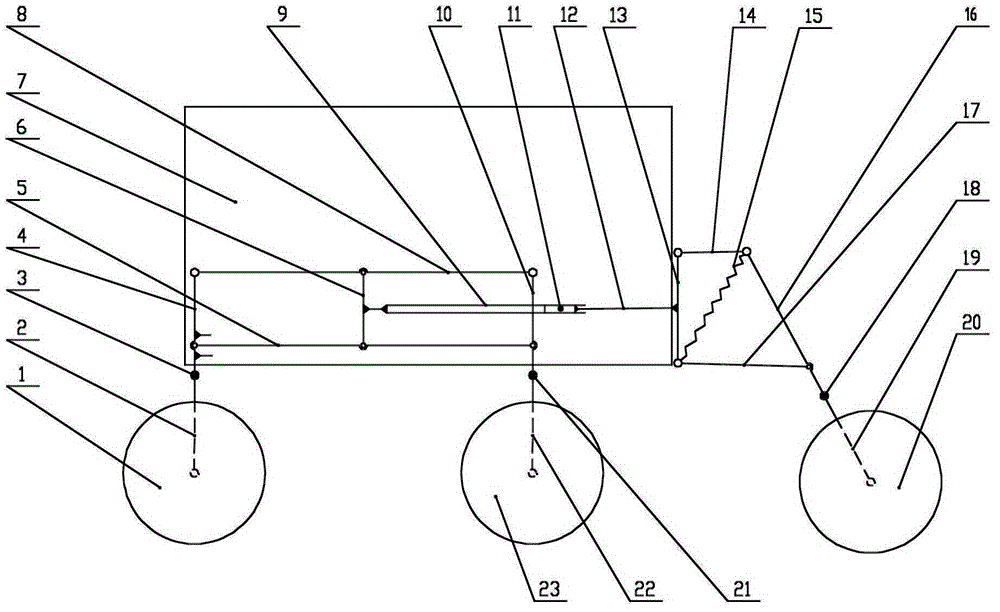
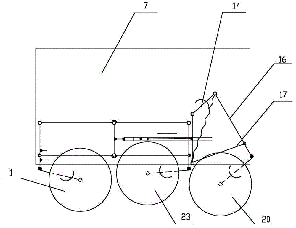
[0007] Specific implementation mode one: combine figure 1 with figure 2 Describe this embodiment, the mechanism of this embodiment includes the first wheel 1, the first rod 2, the first rotation locking device 3, the second rod 4, the third rod 5, the fourth rod 6, the sixth rod 8, and the guide rail 9 , the seventh rod 10, the locking pin 11, the slider 12, the tenth rod 13, the eleventh rod 14, the tension spring 15, the twelfth rod 16, the thirteenth rod 17, the third rotation locking device 18, the first Fourteen bars 19, the third wheel 20, the second rotation locking device 21, the ninth bar 22 and the second wheel 23, one end of the first bar 2 is hinged with the first wheel 1, and the other end of the first bar 2 passes through the first The rotation locking device 3 is connected with one end of the second bar 4, the other end of the second bar 4 is hinged with an end of the sixth bar 8, the other end of the sixth bar 8 is hinged with an end of the seventh bar 10, an...

specific Embodiment approach 2

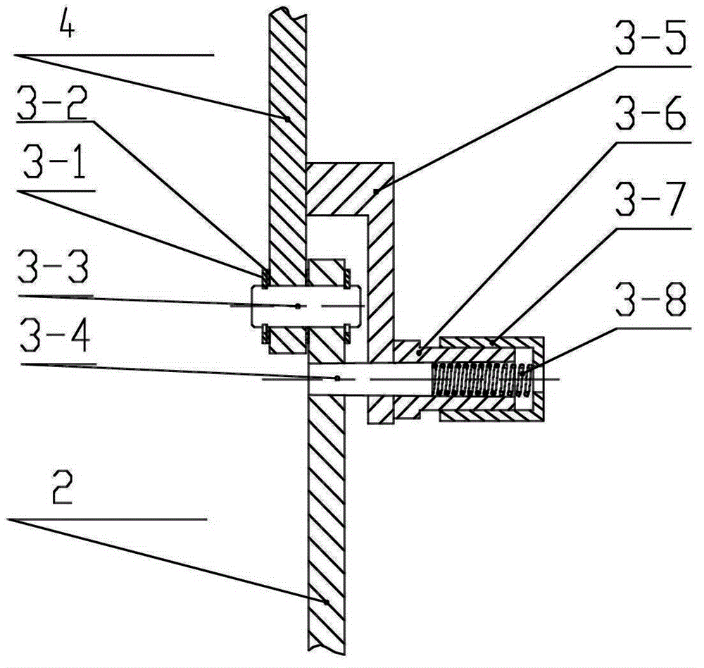
[0009] Specific implementation mode two: combination image 3 Describe this embodiment, the first rotation locking device 3 of this embodiment includes a first snap ring 3-1, a first cylindrical pin 3-3, a first taper pin 3-4, a first support plate 3-5, a first Tapered pin guide sleeve 3-6, first spring cap 3-7, first spring 3-8 and two first spacers 3-2, the first support plate 3-5 is L-shaped, the side of the second rod 4 The wall is affixed to one end of the horizontal section of the first support plate 3-5, and the side wall of the vertical section of the first support plate 3-5 is affixed to one end of the first taper pin guide sleeve 3-6, and the first taper pin The other end of the guide sleeve 3-6 is fitted with the first spring cap 3-7 and the two are threaded, one end of the first taper pin 3-4 is fitted with the first spring 3-8 and this end passes through the first rod 2, The vertical section of the first support plate 3-5 is located in the first taper pin guide s...

specific Embodiment approach 3

[0010] Specific implementation mode three: combination Figure 4 To illustrate this embodiment, the second rotation locking device 21 of this embodiment includes a second snap ring 21-1, a second cylindrical pin 21-3, a second taper pin 21-4, a second support plate 21-5, a second Taper pin guide sleeve 21-6, the second spring cap 21-7, the second spring 21-8 and two second spacers 21-2, the second support plate 21-5 is L-shaped, the side of the seventh bar 10 The wall is affixed to one end of the horizontal section of the second support plate 21-5, and the side wall of the vertical section of the second support plate 21-5 is affixed to one end of the second taper pin guide sleeve 21-6, and the second taper pin The other end of the guide sleeve 21-6 sets the second spring cap 21-7 and the two are threaded, and one end of the second taper pin 21-4 sets the second spring 21-8 and this end passes through the ninth rod 22, The vertical section of the second support plate 21-5 is l...


PUM


Abstract

The invention provides a combined foldable and extendable suspension type six-wheel vehicle-mounted mechanism, relating to a foldable and extendable six-wheel vehicle-mounted mechanism. By adopting the mechanism, the problem that a probe vehicle can not simultaneously have a good folding function and superior mobility performance at present is solved. The mechanism is characterized in that a second rod, a sixth rod, a seventh rod and a third rod form a closed rectangle; one end of a fourth rod is hinged with the middle of the sixth rod and the other end thereof is hinged with the middle of the third rod; the second rod and the fourth rod are arranged in parallel; one end of the seventh rod is hinged with one end of a ninth rod by a second rotary locking device; the other end of the ninth rod is hinged with a second wheel; the side wall of the fourth rod is fixedly connected with one end of a guide rail; the guide rail and a slider are locked by a locking pin; the side wall of the slider is fixedly connected with the side wall of a tenth rod; and the tenth rod, an eleventh rod, a twelfth rod, a thirteenth rod and an extension spring form a spring constrained quadrilateral mechanism. The mechanism is used for planetary exploration.

Description

technical field [0001] The invention relates to a foldable six-wheel vehicle-mounted mechanism. Background technique [0002] At present, researches on planetary exploration vehicles at home and abroad are mainly focused on the mobile performance of its mobile mechanism, and rarely consider the folding function of the vehicle body. Under the constraints of rocket space and launch costs at the current stage, the folding function is of great significance for the rover, which can solve the contradiction between functional diversity and volume. With the implementation of my country's lunar exploration project, the vehicle-mounted mechanism with folding function and superior mobility is receiving more and more attention. Contents of the invention [0003] In order to solve the problem that the current probe vehicle cannot simultaneously have a good folding function and superior mobility, the present invention provides a combined foldable suspension type six-wheel vehicle-mount...

Claims


Application Information

Patent Timeline
Patent Type & Authority Patents(China)
IPC IPC(8): B64G1/16
Inventor 陶建国杨飞邓宗全
Owner HARBIN INST OF TECH
Why Eureka
Try Eureka