Self-control air lifter

A pneumatic lifting and lifting platform technology, applied in the field of lifting platforms, can solve the problems of not being able to meet the requirements, occupying space with electricity, etc.

Inactive Publication Date: 2013-02-06
WUXI LIHU PRESSURIZE TECH CO LTD
View PDF6 Cites 6 Cited by
  • Summary
  • Abstract
  • Description
  • Claims
  • Application Information

AI Technical Summary

Problems solved by technology

[0002] In the process of product production, workers have to process hundreds of products in one iron frame and put them in another iron frame, that is, pick out and process from the upper layer of this iron frame and put them at the bottom of another iron frame until The bottom of this iron frame is sorted out and processed and placed on the top of another iron frame. In order to pick and place the bottom products out of reach, we have to bend down and kowtow to make it together. We have to kowtow thousands of times in one shift, and buy a hydraulic It costs more than 10,000 yuan to adjust the height of the lifting platform placed at the bottom of the iron frame, and it also takes up space with electricity, and the imported spring lifting platform cannot meet the requirements

Method used


Image

  • Self-control air lifter
  • Self-control air lifter
  • Self-control air lifter

Examples


Embodiment Construction

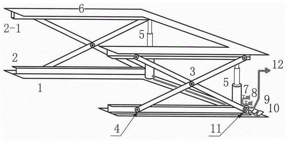
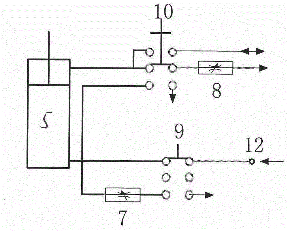
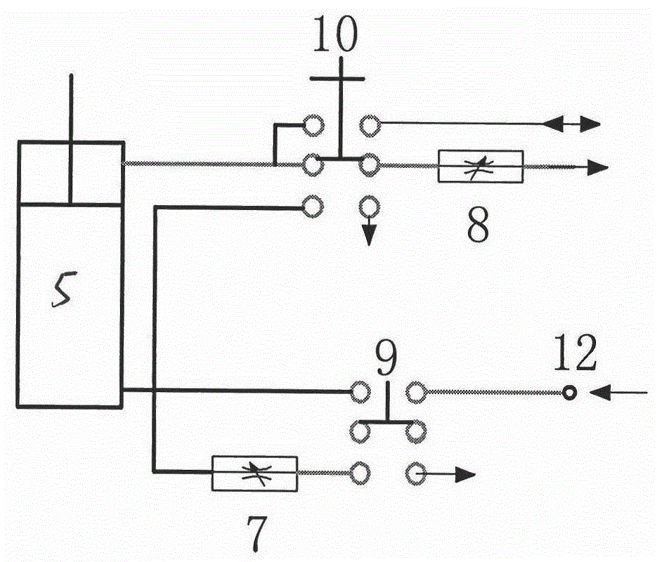
[0009] According to the present invention, the automatic control pneumatic lifting platform figure 1 as shown, figure 2 As shown, the upper and lower fixing mechanism of the self-control pneumatic lifting platform of the present invention is based on the base 1, and the upper chute 2 is installed on the base, and the upper chute 2-1 is installed under the table top 6; The balance fork 3 is installed in the middle of -1, and the balance fork positioning shaft 11 is positioned on one end of the upper chute 2-1 of the glide groove 2. The cylinder 5 lifts and slides, and the balance fork 3 keeps the table 6 stable when it rises and falls; the pneumatic lifting mechanism is composed of the cylinder 5 and is installed between the base and the table 6 to support the height of the table 6; the pneumatic control mechanism is used by the descending throttle valve 7 for the cylinder 5. The air flow adjustment when descending under the action of gravity is installed on the lower part of...


PUM


Abstract

The invention discloses a self-control air lifter which is laid at the bottom of an iron frame when in use, and is characterized by comprising a longitudinal fixing mechanism, a double-fork balancing mechanism, a pneumatic lifting mechanism and a mechanism control mechanism. The self-control air lifter adopts compressed air with non pollution and transportable properties as lifting kinetic energy, adopts a throttling valve and a foot self-locking reversing valve to control inlet and outlet flow of the compressed air to adjust the height of the air lifter in a self-control way, and can manipulate a foot lock valve to correct the height of the air lifter when the lifting speed or the lowering speed does not meet operation speed, so that required height is corrected to a proper position, the motion of bending down and head colliding of workers is avoided, the labor intensity of the workers is reduced with low investment, and the blank in the air lifter is filled.

Description

technical field [0001] The invention relates to a lifting platform, in particular to a pneumatic lifting platform. Background technique [0002] In the process of product production, workers have to process hundreds of products in one iron frame and put them in another iron frame, that is, pick out and process from the upper layer of this iron frame and put them at the bottom of another iron frame until The bottom of this iron frame is sorted out and processed and placed on the top of another iron frame. In order to pick and place the bottom products out of reach, we have to bend down and kowtow to make it together. We have to kowtow thousands of times in one shift, and buy a hydraulic It costs more than 10,000 yuan to adjust the height of the lifting table placed at the bottom of the iron frame, and it also takes up space with electricity. The imported spring lifting table cannot meet the requirements. Contents of the invention [0003] The self-controlled pneumatic lift...

Claims


Application Information

Patent Timeline
Patent Type & Authority Applications(China)
IPC IPC(8): B66F7/08B66F7/28
Inventor 邵宏
Owner WUXI LIHU PRESSURIZE TECH CO LTD
Why Eureka
Try Eureka