Flat opening mechanism with moving pair
A technology of opening mechanism and moving pair, which is applied in the direction of cam opening mechanism, loom, textile, etc., can solve the problem of being limited to below 600 rpm, and achieve the effect of avoiding damage
- Summary
- Abstract
- Description
- Claims
- Application Information
AI Technical Summary
Benefits of technology
Problems solved by technology
Method used
Image

Examples
Embodiment 1
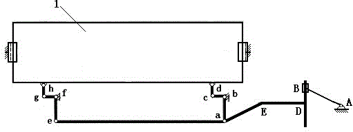
[0033] see figure 1 As shown, a flat opening mechanism with a moving pair is composed of a crank moving guide rod mechanism, a push rod, and a swing rod mechanism;
[0034] The two ends of the pull rod ae are respectively hinged with a first swing rod ab and a second swing rod ef, and the first swing rod ab and the second swing rod ef are respectively hinged with a third swing rod bc and a fourth swing rod fg, the third swing link bc and the fourth swing link fg respectively hinge the first link cd and the second link gh, the first link cd and the second link gh are connected to the heald frame 1 hinged;
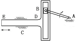
[0035] see figure 2 As shown, the crank moving guide rod mechanism includes a T-shaped first guide rod DE, and a chute is opened on the first guide rod DE, and a slider B is arranged in the chute, and the slider B It is hinged with a crank AB; the length of the first rack AC of the crank moving guide rod mechanism is greater than twice the length of the first crank AB; ...
Embodiment 2
[0040] see Figure 4 As shown, a flat opening mechanism with a moving pair is composed of a first crank guide rod pendulum mechanism, a push rod, and a pendulum mechanism;
[0041] The two ends of the pull rod ae are respectively hinged with a first swing rod ab and a second swing rod ef, and the first swing rod ab and the second swing rod ef are respectively hinged with a third swing rod bc and a fourth swing rod fg, the third swing link bc and the fourth swing link fg respectively hinge the first link cd and the second link gh, the first link cd and the second link gh are connected to the heald frame 1 hinged;
[0042] see Figure 5 As shown, the first crank guide bar pendulum mechanism includes a second crank FG, the second crank FG is hinged to a second guide rod GH, and the first pendulum block I is arranged on the second guide rod GH ; The length of the second frame FI of the crank guide pendulum mechanism is greater than 2 times the length of the second crank FG;
...
Embodiment 3
[0047] see Figure 7 As shown, a flat opening mechanism with a moving pair is composed of a six-bar crank guide rod pendulum mechanism, a push rod, and a pendulum mechanism;
[0048] The two ends of the pull rod ae are respectively hinged with a first swing rod ab and a second swing rod ef, and the first swing rod ab and the second swing rod ef are respectively hinged with a third swing rod bc and a fourth swing rod fg, the third swing link bc and the fourth swing link fg respectively hinge the first link cd and the second link gh, the first link cd and the second link gh are connected to the heald frame 1 hinged;
[0049] see Figure 8 As shown, the six-bar crank guide pendulum mechanism is composed of a second crank guide pendulum mechanism and a double rocker mechanism in series, including a third crank JK and a rocker MN, and the third crank JK is connected to a first The three guide rods KL are hinged, and the third guide rod KL is provided with a second pendulum O; th...
PUM
 Abstract
Description
Claims
Application Information
 - R&D
- Intellectual Property
- Life Sciences
- Materials
- Tech Scout
- Unparalleled Data Quality
- Higher Quality Content
- 60% Fewer Hallucinations
Browse by: Latest US Patents, China's latest patents, Technical Efficacy Thesaurus, Application Domain, Technology Topic, Popular Technical Reports.
© 2025 PatSnap. All rights reserved.Legal|Privacy policy|Modern Slavery Act Transparency Statement|Sitemap|About US| Contact US: help@patsnap.com