
Steel rail temporary fixing structure and longitudinal blocking groove block installation and construction method

A temporary fixing and rail technology, applied in the directions of track, track laying, track maintenance, etc., can solve the problems of difficulty in initial commissioning, maintenance and replacement of rails, poor contact between wheels and rails, and large rail wear. Longevity, the effect of improving the contact relationship

Inactive Publication Date: 2019-12-27
成都天府轨谷科技有限公司
View PDF0 Cites 0 Cited by
  • Summary
  • Abstract
  • Description
  • Claims
  • Application Information

AI Technical Summary

Problems solved by technology

[0004] The current track system uses fastener system to support the rail. The fastener system supports the rail discontinuously. The rail has a suspended section. When the train runs on the rail at a certain speed, the rail will generate a pinned-pinned vibration mode. The wheel-rail contact relationship is not good, and the rail wears a lot
If the fastener system is canceled and the continuous support track system is adopted, the initial commissioning and later maintenance and replacement of the rails will be very difficult.

Method used


Image

  • Steel rail temporary fixing structure and longitudinal blocking groove block installation and construction method
  • Steel rail temporary fixing structure and longitudinal blocking groove block installation and construction method
  • Steel rail temporary fixing structure and longitudinal blocking groove block installation and construction method

Examples


Embodiment 1

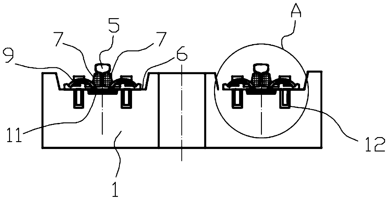
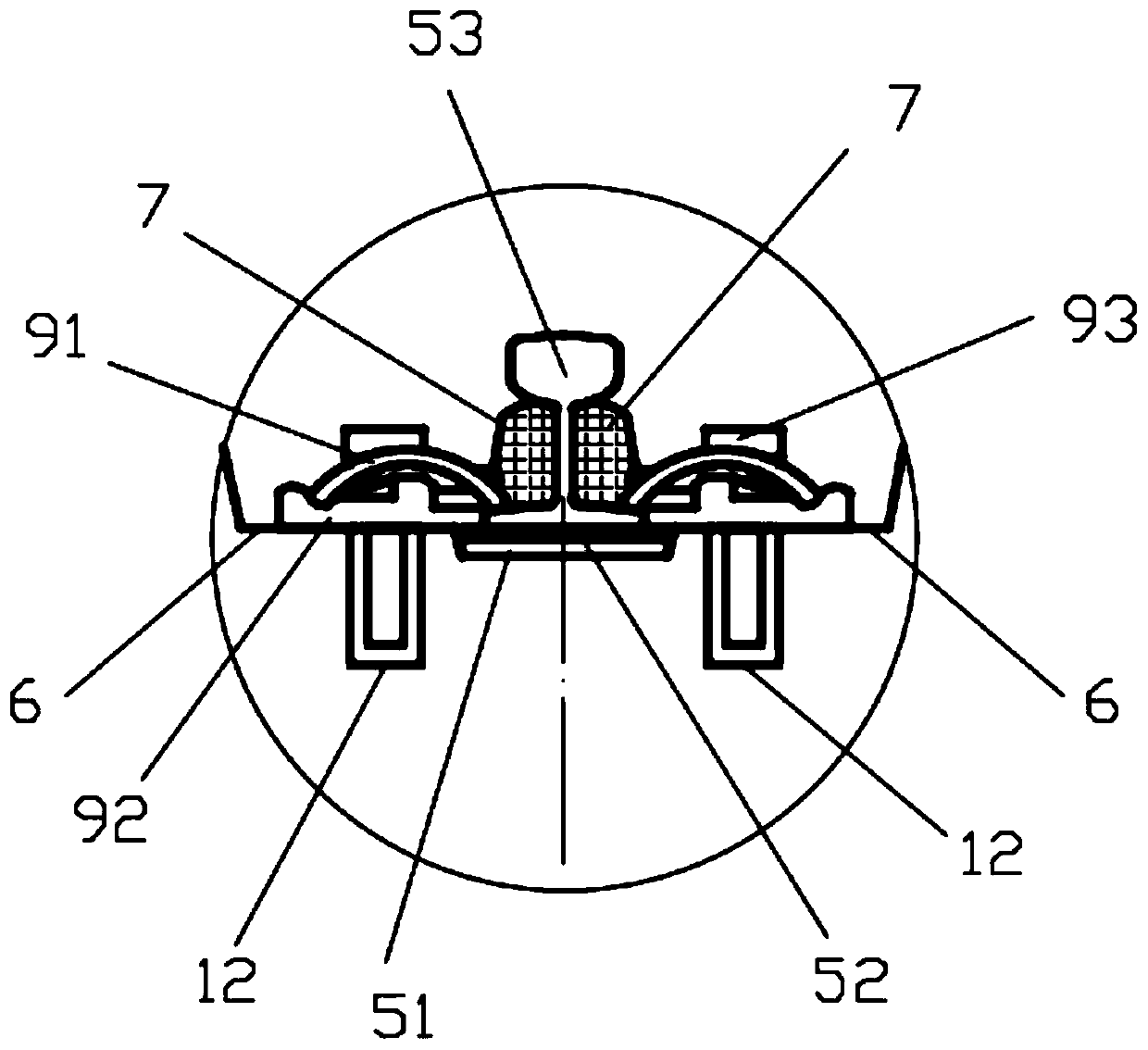
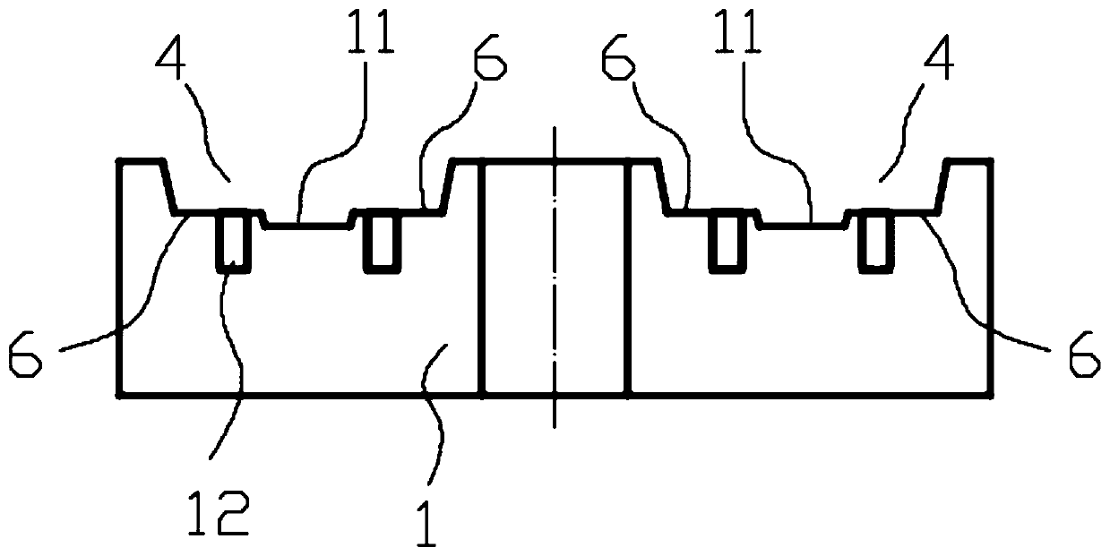
[0033] Such as figure 1 , 2 As shown, the rail temporary fixing structure disclosed in the first embodiment includes a plate body 1, a rail assembly 5 and a temporary fastener 9. There are two longitudinal grooves 4 on the top surface of the plate body 1, and the groove bottom of each longitudinal groove 4 There is a concave rail bearing groove 11 formed in the center. The rail assembly 5 includes a rail 53, which is placed in the rail bearing groove 11, and the rail 53 is fixed on the plate body 1 through a plurality of temporary fasteners 9, and bolt sleeves 12 are pre-embedded on the steps 6 on both sides of the rail bearing groove 11 , the temporary fastener 9 is bolted to the plate body 1.

[0034] The rail assembly 5 also includes a height-adjusting backing plate 52 and a long elastic backing plate 51, the long elastic backing plate 51 is spread on the bottom of the rail groove 11, the rail 53 is pressed on the height-adjusting backing plate 52, and the height-adjustin...

Embodiment 2

[0046]The difference between this embodiment and Embodiment 1 is that: Figure 7 As shown, in this embodiment, the longitudinal groove 4 of the plate body 1 is a low-position embedded groove, and the longitudinal groove block 2 is partially embedded in the plate body 1, and most (for example, 77%) of the longitudinal groove block 2 is exposed to the The top surface of the plate body 1.

[0047] The rail temporary fixing structure of the present invention can temporarily fix the rail components, facilitate the adjustment of the rails, and is suitable for the temporary fixing of the rails during the construction of the continuous support rail system; after the rail line is stabilized and finally fine-tuned, install the longitudinal groove block and Pouring polymer damping materials to accurately position and permanently fix the rail components, provide continuous support and continuous locking for the rails, basically eliminate the vibration source generated by the rails under t...


PUM


Abstract

The present invention relates to a steel rail temporary fixing structure and a longitudinal blocking groove block installation and construction method. The steel rail temporary fixing structure comprises a plate body, a steel rail assembly, the temporary fasteners and the noise reduction blocks, the steel rail assembly comprises a steel rail, and the top face of the plate body is provided with a rail bearing groove formed in an inwards-concave manner. The steel rail is arranged in the rail bearing grooveand is fixed to the plate body through the temporary fasteners, the noise reduction blocksare installed between every two longitudinally-adjacent temporary fasteners and at the inner side and the outer side of the steel rail, the bottoms of the noise reduction blocks are embedded between the steel rail assembly and the groove wall of the rail bearing groove, and the tops of the noise reduction blocks extend to the positions below a rail head. The steel rail temporary fixing structure and the longitudinal blocking groove block installation and construction method are suitable for temporarily fixing the steel rail during the construction process of a continuous supporting rail system, after a rail line is stabilized, the temporary fasteners are disassembled, then the longitudinal blocking groove blocks are installed, and a polymer damping material is poured to fix the steel railassembly permanently, so that the steel rail can be supported and locked continuously, the vibration source generated by the steel rail under the external forces can be eliminated basically, the wheelrail contact relation can be improved, the abrasion of a wheel rail is greatly reduced, and the service life of the wheel rail is prolonged.

Description

technical field [0001] The invention relates to the technical field of railway tracks, in particular to a temporary rail fixing structure and a construction method for installing longitudinal groove blocks. Background technique [0002] The track slab refers to a new type of under-rail component whose structure is a slab body, used to support and fix the rail, and distribute the load transmitted by the train through the rail to the sub-slab base. [0003] Double-block ballastless track, CRTS I type, CRTS II type, CRTS III type slab ballastless track are all used in my country's high-speed railway or passenger dedicated line. Among them, the track slabs of CRTS I, CRTS II and CRTS III slab ballastless tracks are all prestressed structures. [0004] The current rail system uses fastener system to support the rail. The fastener system supports the rail discontinuously. The rail has a suspended section. When the train runs on the rail at a certain speed, the rail will produce a...

Claims


Application Information

Patent Timeline
Patent Type & Authority Applications(China)
IPC IPC(8): E01B29/40
CPCE01B29/40
Inventor 钱振地毕小毛肖大庆林晓波张长春肖伟肖毅王平刘学毅苗昌荗覃婷税卓平陈逊张忠杨建明邓玉竹陈宝林魏运鸿孙春平杨刚罗炯任志江刘光圣赵瑞亮王乃勇张日鹏周炼谭斌杨正国黎开政李小军
Owner 成都天府轨谷科技有限公司
Learn More