
Input and output power resonance control method of PWM (pulse width modulation) rectifier under voltage unsymmetrical fault

A voltage asymmetry, input and output technology, applied in the direction of conversion of AC power input to DC power output, output power conversion device, electrical components, etc., can solve the problems of increasing the amount of calculation of the control scheme and the inability to realize the unit power factor operation of the system, etc. , to achieve the effect of guaranteed input and output quality, simple algorithm, and easy implementation

Inactive Publication Date: 2013-02-06
HENAN NORMAL UNIV
View PDF7 Cites 17 Cited by
  • Summary
  • Abstract
  • Description
  • Claims
  • Application Information

AI Technical Summary

Problems solved by technology

Although this method avoids the calculation of positive and negative sequences in the current inner loop, in order to calculate the given value of positive and negative sequence currents, it is necessary to decompose the positive and negative sequences of each component in the system, which increases the calculation amount of the control scheme
In addition, this method cannot achieve unity power factor operation of the system

Method used


Image

  • Input and output power resonance control method of PWM (pulse width modulation) rectifier under voltage unsymmetrical fault
  • Input and output power resonance control method of PWM (pulse width modulation) rectifier under voltage unsymmetrical fault
  • Input and output power resonance control method of PWM (pulse width modulation) rectifier under voltage unsymmetrical fault

Examples


Embodiment Construction

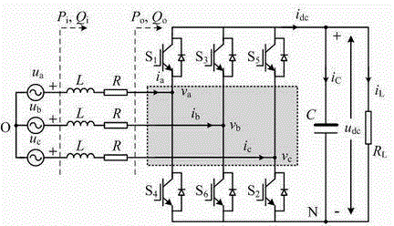
[0013] The present invention will be further described below in conjunction with the accompanying drawings. The main circuit structure of the three-phase voltage-type PWM converter is as follows: figure 1 as shown, figure 1 middle, P i , Q i and P o , Q o are grid input power and rectifier output power, respectively, u a , u b , u c is a three-phase voltage source on the AC side, i a , i b , i c is the input current of the three-phase AC side, v a , v b , v c is the three-phase voltage at the input side of the power bridge, u dc is the DC side voltage, O is the grid midpoint, L and R are the incoming inductance and its equivalent resistance, respectively, C is the DC bus capacitor. In an ideal situation, it can be considered that the input power of the grid is equal to the sum of the output power of the rectifier and the power consumed by the incoming inductance and equivalent resistance, and the output power of the rectifier is equal to the su...


PUM


Abstract

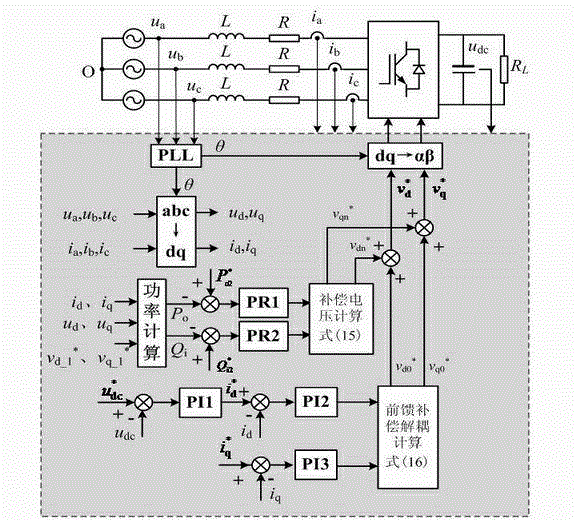
The invention discloses an input and output power resonance control method of a PWM (pulse width modulation) rectifier under a voltage unsymmetrical fault. The input and output power resonance control method of the PWM rectifier under the voltage unsymmetrical fault comprises the following steps of: calculating the difference between given pulse values of second harmonic frequencies of output active power and input reactive power of a system and practical values of active power and reactive power of the system; obtaining second harmonic frequency offset items of the output active power and the input reactive power respectively through a proportion resonance controller and by second harmonic frequency offset voltage calculation, adding a voltage reference value obtained by conventional vector control to the second harmonic frequency offset items respectively; performing reverse Park transformation by taking a power grid voltage position angle as a transformation angle to obtain a voltage in two-phase static coordinates; and after voltage signals are subjected to space vector pulse width modulation, generating on-and-off signals for controlling power instruments. By using the input and output power resonance control method of the PWM rectifier under the voltage unsymmetrical fault, pulses of the input reactive power and the output active power of the PWM rectifier can be directly compensated, and unit power factor operation and direct current busbar voltage of the system are stably controlled.

Description

[0001] technical field [0002] The invention relates to a control method of a voltage-type PWM rectifier under unbalanced grid voltage, which belongs to the control field of power electronic power conversion devices, in particular to a method for controlling input and output power resonance of a PWM rectifier under a voltage asymmetry fault. Background technique [0003] Three-phase voltage-type pulse width modulation rectifiers are widely used in the fields of static var compensation, high-voltage direct current transmission, active power filtering, electric drive and grid-connected power generation of renewable energy. Under normal grid conditions, the rectifier can operate at unity power factor and output a stable DC bus voltage. However, when the three-phase voltage of the power grid is unbalanced due to the unbalanced fault of the grid voltage, the input reactive power of the PWM rectifier designed based on the voltage three-phase balance condition will have double fre...

Claims


Application Information

Patent Timeline
Patent Type & Authority Applications(China)
IPC IPC(8): H02M7/219H02M1/14
Inventor 施艳艳王萌
Owner HENAN NORMAL UNIV
Learn More