
Coupler

A technology of couplings and retainers, which is applied in the direction of couplings, electrochemical generators, transportation and packaging, etc., and can solve problems such as liquid leakage in the joints of couplings

Active Publication Date: 2015-05-06
TOYO SEIKAN KAISHA LTD
View PDF8 Cites 0 Cited by
  • Summary
  • Abstract
  • Description
  • Claims
  • Application Information

AI Technical Summary

Problems solved by technology

[0004] In such a coupler, if the connected state of the socket and the plug is not reliably maintained, leakage of liquid or the like occurs at the joint part of the coupler.

Method used


Image

  • Coupler
  • Coupler
  • Coupler

Examples


Embodiment Construction

[0043] Hereinafter, embodiments of the present invention will be described in detail based on the drawings.

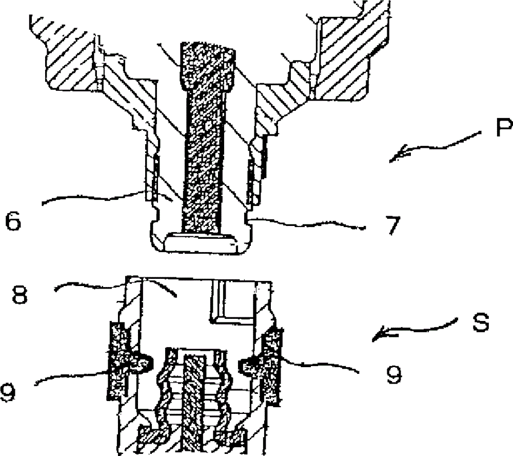
[0044] The coupler 10 is composed of a socket S10 and a plug P10 which is fitted and connected to the socket S10. For example, the socket S10 is provided on the main body side of the methanol fuel cell, and the plug P10 is provided on the cartridge side serving as a methanol container to communicate with each other to the main body. It is used to replenish fuel on the side, or to be replaced together with the cartridge, and the main part is made of metal materials and non-metal materials, such as polypropylene, polyphenylene sulfide, polyacetal and other synthetic resins.

[0045] In the following description, the upper and lower sides on the drawings will be described as a reference, but the actual mounting direction to the container body is not limited at all, and it may be implemented in any direction.

[0046] In the socket S10 of the coupler 10, the component F th...


PUM


Abstract

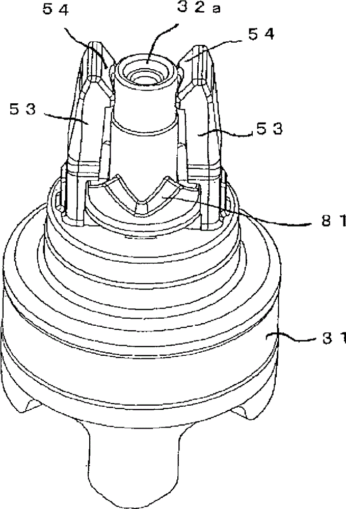
Coupling holding means 50 comprising retainers 53 and retainer engaging portions 52 for holding a coupled state is provided between a socket S10 and a plug P10 of a coupler. Engaging pawl portions 54 are formed on the inner sides of a pair of retainers 53 provided on both sides of a nozzle portion 32. By causing the retainers 53 to move outwardly in a coupling operation, a gap between the retainers 53 and the nozzle portion 32 can be made small. By forming interference preventing portions 58 in the engaging pawl portions 54, the retainers 53 can be provided at a smaller interval than the outer diameter of the nozzle portion 32 whereby the coupler can be made even more compact. Further, by forming the retainers 53 higher than the foremost end portion of the nozzle portion 32, the nozzle portion 32 can be protected by the retainers 53 even in an unexpected event such as falling and damage will not extend directly to the nozzle portion 32.

Description

technical field [0001] The present invention relates to a detachably connected coupler composed of a socket and a plug, which can easily transfer a liquid or the like from a container to a container or the like on the main body side, or can reliably maintain the connected state when the container is replaced together. The structure can be used for a connector with a smaller inner diameter of the connection hole on the socket side, and is particularly suitable for being provided between the cartridge container of the methanol fuel cell and the fuel cell main body. Background technique [0002] In the past, it was often necessary to replenish liquids such as raw materials, which decreased with the operation or use of the equipment, by connecting a cassette container to a container provided on the equipment main body side to transfer liquids such as raw materials, or by connecting the container on the equipment main body side to supply liquids such as raw materials. It is suppl...

Claims


Application Information

Patent Timeline
Patent Type & Authority Patents(China)
IPC IPC(8): F16L37/08F16L37/32
CPCF16L37/0985H01M8/04186H01M8/04201H01M8/04208H01M8/1011Y10T137/87957Y10T137/9029F16L37/40Y02E60/50
Inventor 官野稔吉弘宪司
Owner TOYO SEIKAN KAISHA LTD
Learn More