
Vehicle seat

a technology for vehicles and seats, applied in vehicle seats, vehicle parts, vehicle arrangements, etc., can solve the problems of inability to measure the weight of seated occupants on the vehicle seat with respect, and difficulty in providing a load sensor between the vehicle floor and the seating portion of the vehicle seat, so as to prevent damage, reduce the center of gravity, and measure the weight of seated occupants

Active Publication Date: 2018-08-28
TS TECH CO LTD +1
View PDF6 Cites 7 Cited by
  • Summary
  • Abstract
  • Description
  • Claims
  • Application Information

AI Technical Summary

Benefits of technology

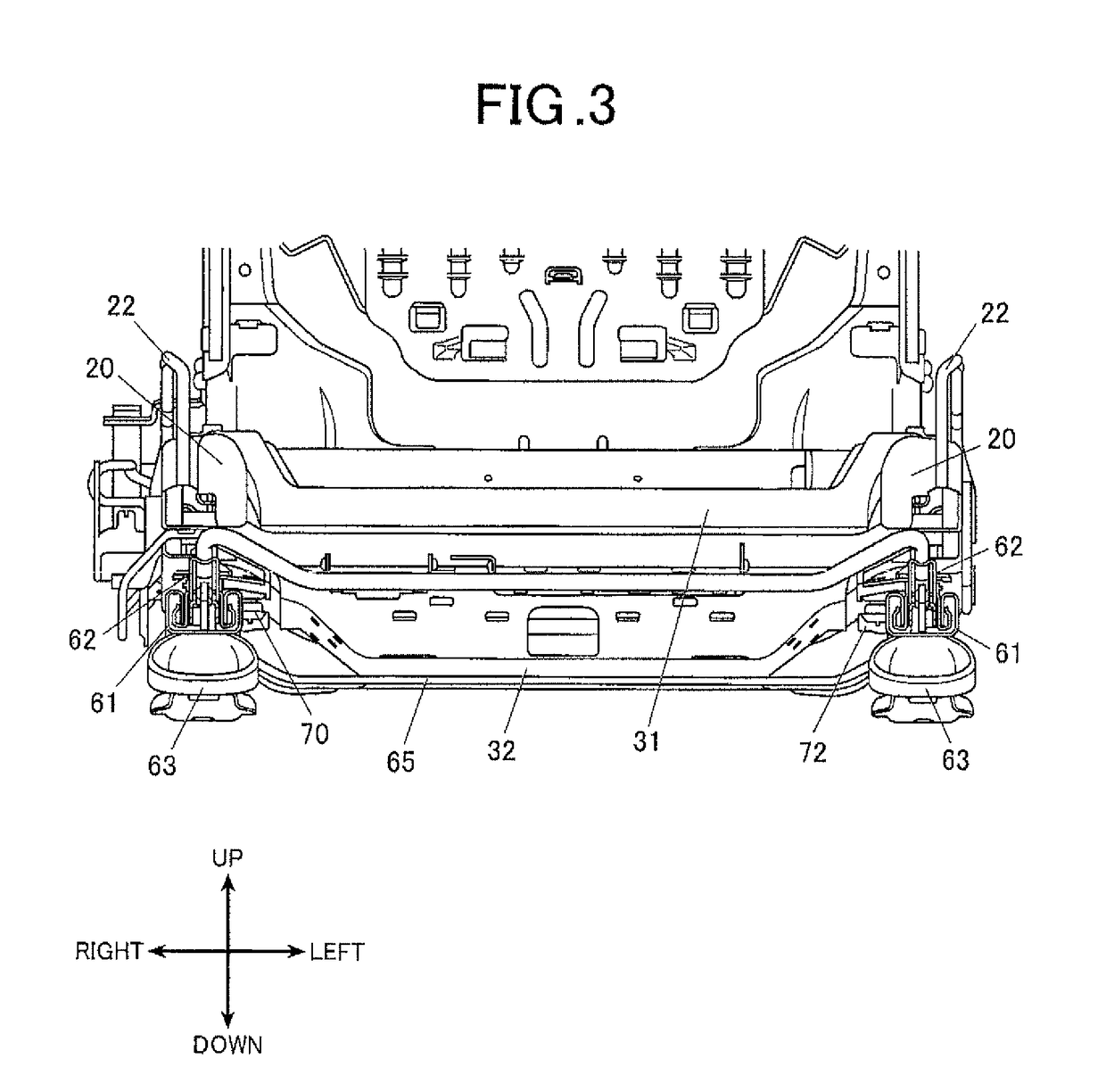
[0020]In the invention according to claim 1, since the seat portion is provided below the load sensor, the weight of a seated occupant can be measured even when the seat portion of the vehicle seat is provided as low as possible and the center of gravity can be lowered in a vehicle seat including a load sensor.
[0021]In the invention according to claim 2, since the protecting member which protects the load sensor is provided between the load sensor and the seat portion, even when a pad member of the vehicle seat sags when an occupant sits on the vehicle seat, the pad member can be prevented from pressing the load sensor.
[0022]Therefore, the load sensor can be prevented from being damaged due to the pressure to the load sensor applied by the pad member of the vehicle seat.
[0023]In the invention according to claim 3, since the protecting member is a linear member and is formed so as to surround the load sensor, forming the protecting member is easy.
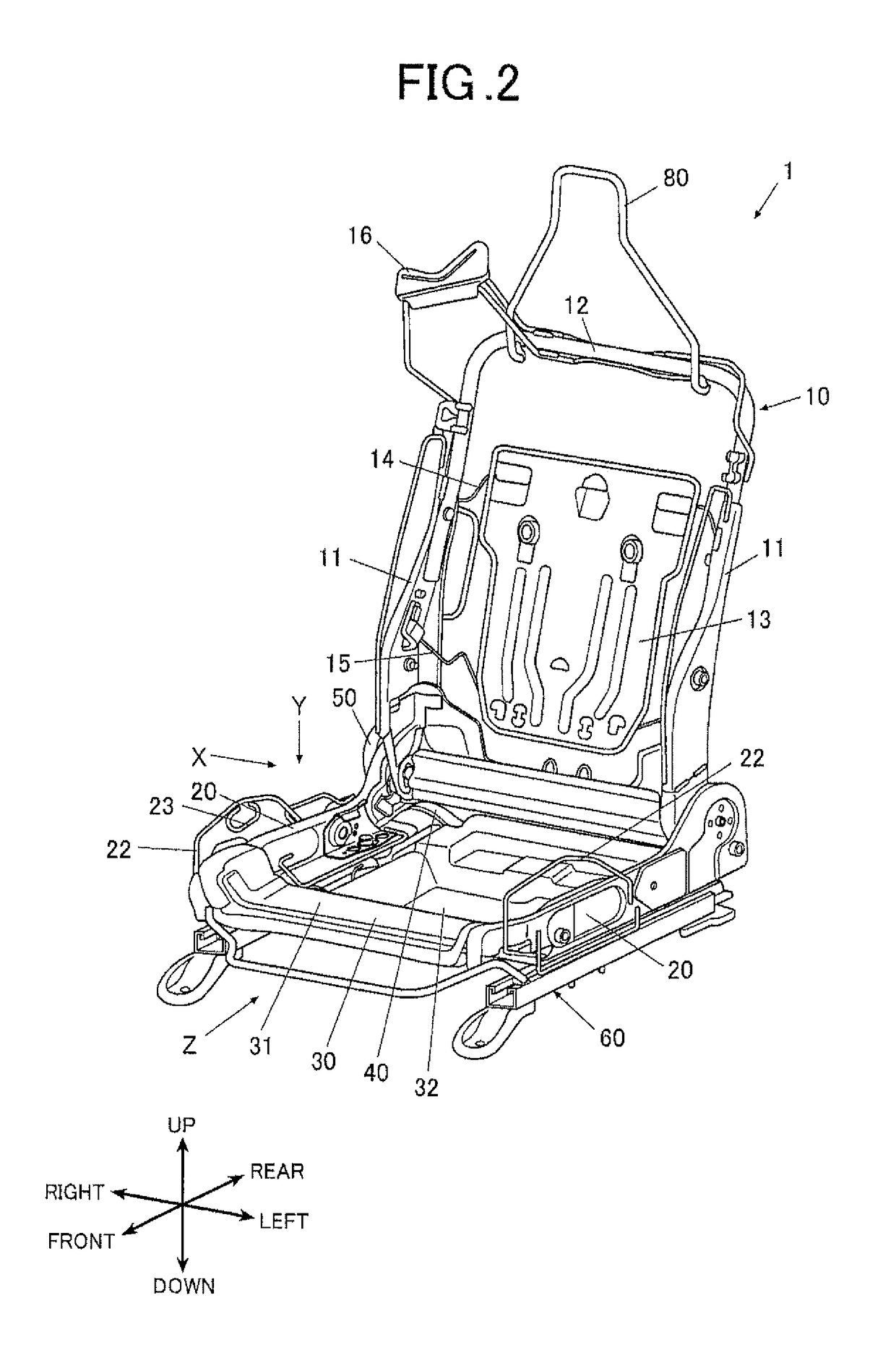
[0024]In the invention according to claim 4, since the seat portion is formed so as to be accommodated between the pair of side frames, the center of gravity of the vehicle seat can be preferably lowered without increasing the width of the vehicle seat.
[0025]In the invention according to claim 5, since the protecting member is formed such that the rear end of the protecting member is positioned in rear of the rear end of the load sensor and such that the front end of the protecting member is positioned in front of the front end of the load sensor, the surrounding of the load sensor can be protected and the damage to the load sensor can be preferably prevented.

Problems solved by technology

However, in the case of a sports car type vehicle in which a seating portion of a vehicle seat is provided as low as possible, there is a problem that it is difficult to provide a load sensor between a vehicle floor and a seating portion of the vehicle seat and it is not possible to measure the weight of an occupant seated on the vehicle seat with respect to the device disclosed in Patent Document 1 described above.

Method used


Image

  • Vehicle seat
  • Vehicle seat
  • Vehicle seat

Examples


Embodiment Construction

[0037]Hereinafter, an embodiment of the present invention will be described with reference to the drawings. Though various technical limitations which are preferable to carry out the present invention are added to the embodiment described below, the scope of the invention is not limited to the following embodiment and the illustrated examples.

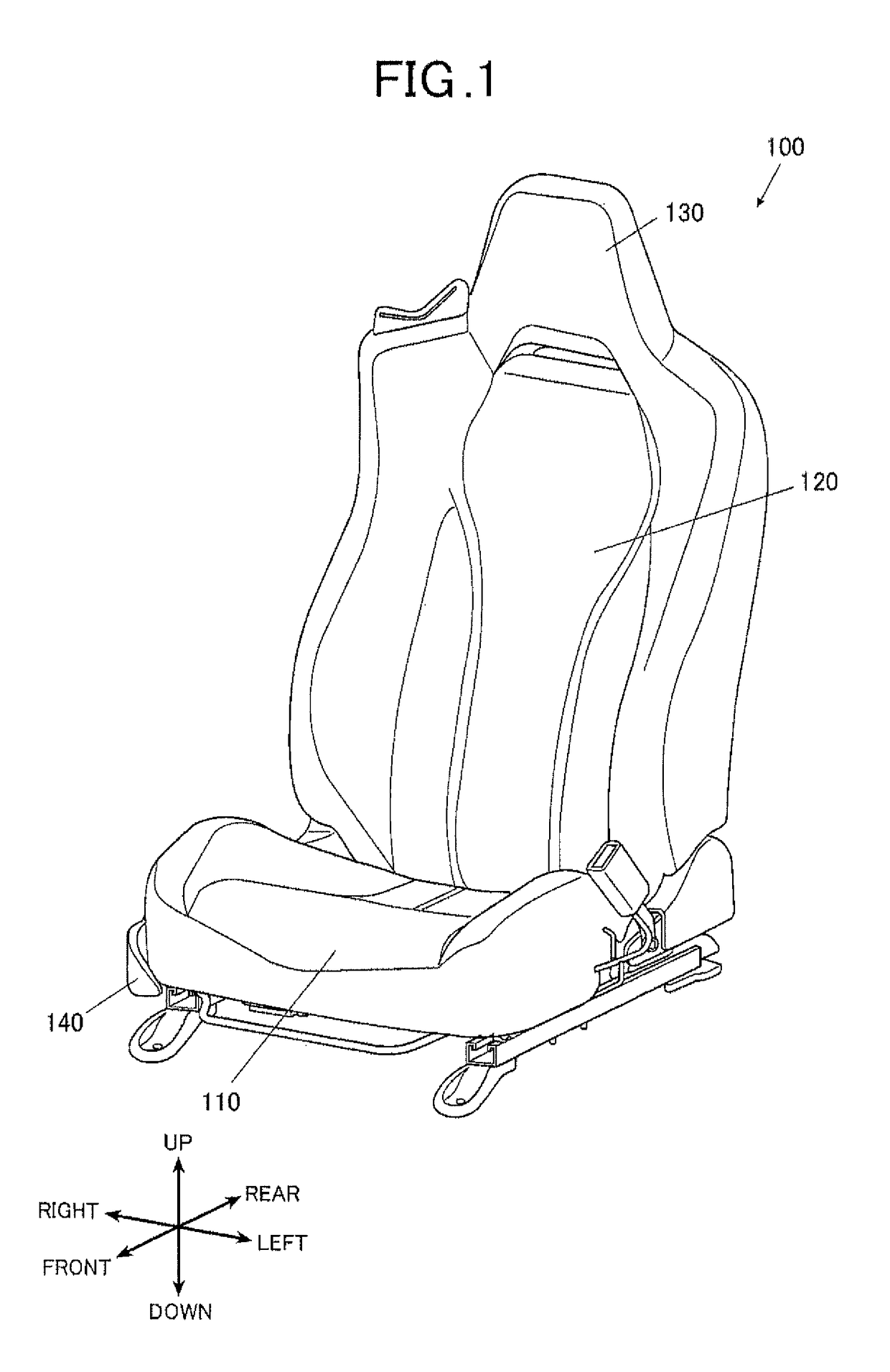
[0038]FIG. 1 is a perspective view of a vehicle seat according to the present embodiment. The up, down, left, right, front and rear arrows respectively indicate the directions seen from a seated person (occupant) seated on the vehicle seat.

[0039]As shown in FIG. 1, the vehicle seat 100 includes a seat cushion 110 on which a seated person is to be seated, a seatback 120 attached to the rear end of the seat cushion 110 pivotally in front and rear directions and which supports the seated person's back, and a headrest 130 which supports the seated person's head. The vehicle seat 100 also includes a side cover member 140 which protects the right sid...


PUM


Abstract

A vehicle seat includes a pair of side frames and a load sensor. The load sensor is provided at a lower portion of the side frame or below the side frame. The vehicle seat further includes a supporting member which is connected to the side frame and which supports a seated person. The supporting member includes a seat portion which receives a weight of a seated person. The seat portion is provided below the load sensor.

Description

TECHNICAL FIELD[0001]The present invention relates to a vehicle seat.BACKGROUND ART[0002]Recently, in order to improve the performance of safety systems such as an airbag, the operations of some safety systems are controlled in accordance with the weight of an occupant seated on a vehicle seat. As a conventional device which measures the weight of a seated occupant, a device is proposed which includes a load sensor between a vehicle floor and a seating portion of a vehicle seat to measure the weight of an occupant based on the amount of deformation of the vehicle seat (refer to Patent Document 1, for example).PRIOR ART DOCUMENTPatent Document[0003]Patent Document 1: JP 2014-221605 ASUMMARY OF INVENTIONProblem to Be Solved By the Invention[0004]However, in the case of a sports car type vehicle in which a seating portion of a vehicle seat is provided as low as possible, there is a problem that it is difficult to provide a load sensor between a vehicle floor and a seating portion of th...

Claims


Application Information

Patent Timeline
Patent Type & Authority Patents(United States)
IPC IPC(8): B60N2/68B60N2/00
CPCB60N2/68B60N2/002
Inventor INOUE, TAKAYUKIHAGE-HASSAN, SOUHEILMORRIS, TODDNAKAMURA, YUJIOKADA, MASAKAZU
Owner TS TECH CO LTD
Learn More